
Method for controlling a touch sensor

a touch sensor and control method technology, applied in the direction of digital data processing details, instruments, electric digital data processing, etc., can solve the problems of noise disturbance of electrical signals, errors in sensing circuits using dc excitation, etc., and achieve the effect of easy demodulation of detected electrical signals

Inactive Publication Date: 2015-01-01
SONY MOBILE COMM AB
View PDF5 Cites 90 Cited by
  • Summary
  • Abstract
  • Description
  • Claims
  • Application Information

AI Technical Summary

Benefits of technology

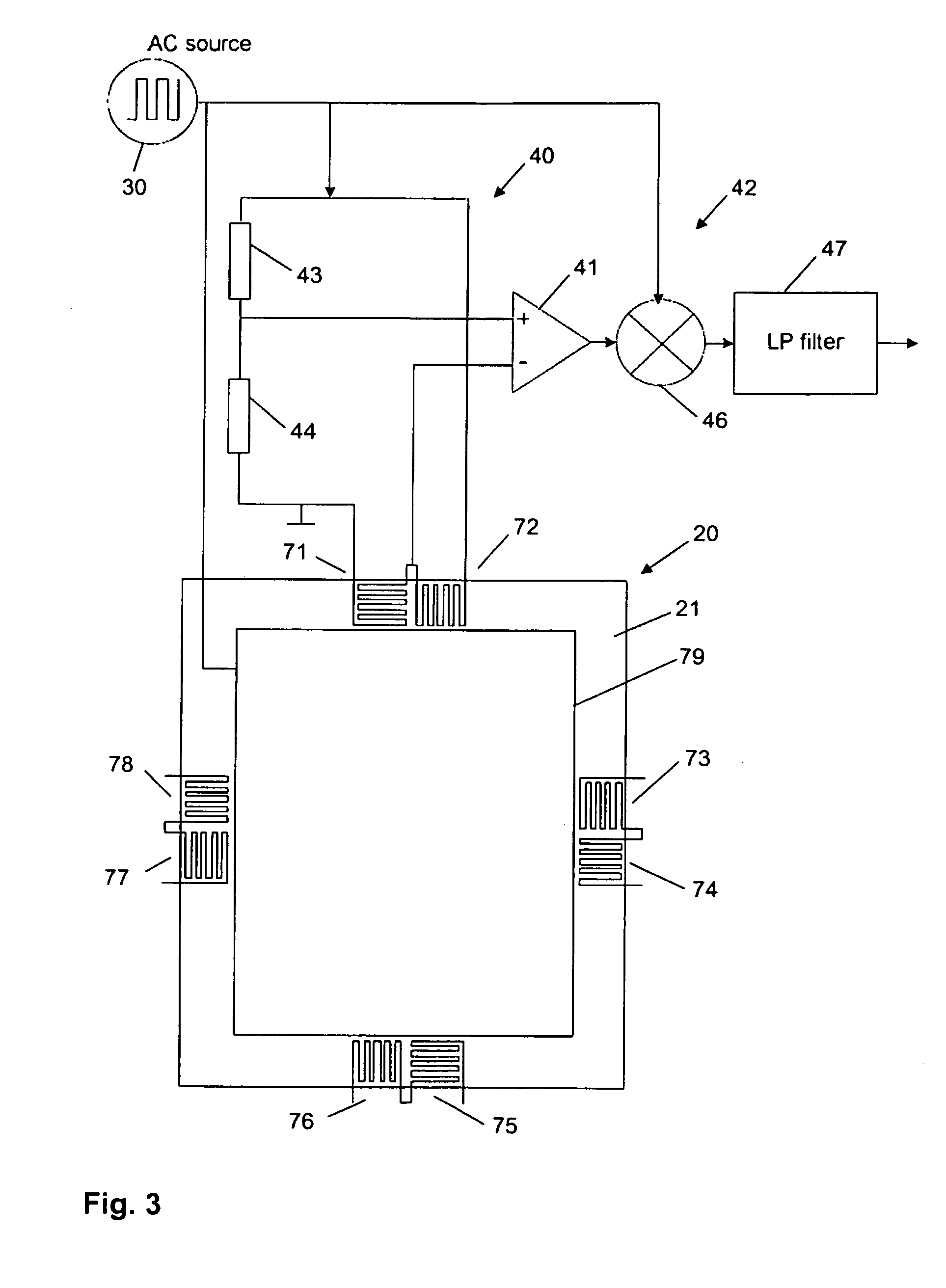
The patent describes a method for sensing force and touch using an electrically conductive sensor structure. The sensor detects a change in electrical resistance when force is applied, and this change is filtered out using an alternating electrical signal and a low-pass filter to reduce noise. The method does not require synchronization between touch and force sensing, and can be done at the same time. The sensor structure can be designed using a Wheatstone bridge to detect small changes in resistance. The method simplifies the hardware and software required for the sensor.

Problems solved by technology

However, the electrical signal may be disturbed by noise, DC drifts in the electronics and line noise pickup.
A sensing circuit that uses a DC excitation may be plagued by errors caused by thermocouple effects, 1 / f noise, DC drifts in the electronics, and line noise pickup.

Method used


Image

  • Method for controlling a touch sensor
  • Method for controlling a touch sensor
  • Method for controlling a touch sensor

Examples


Embodiment Construction

[0020]In the following, exemplary embodiments of the invention will be described in more detail. It has to be understood that the following description is given only for the purpose of illustrating the principles of the invention and is not to be taken in a limiting sense. Rather, the scope of the invention is defined only by the appended claims and is not intended to be limited by the exemplary embodiments hereinafter.

[0021]It is to be understood that the features of the various exemplary embodiments described herein may be combined with each other unless specifically noted otherwise. Same reference signs in the various drawings and the following description refer to similar or identical components.

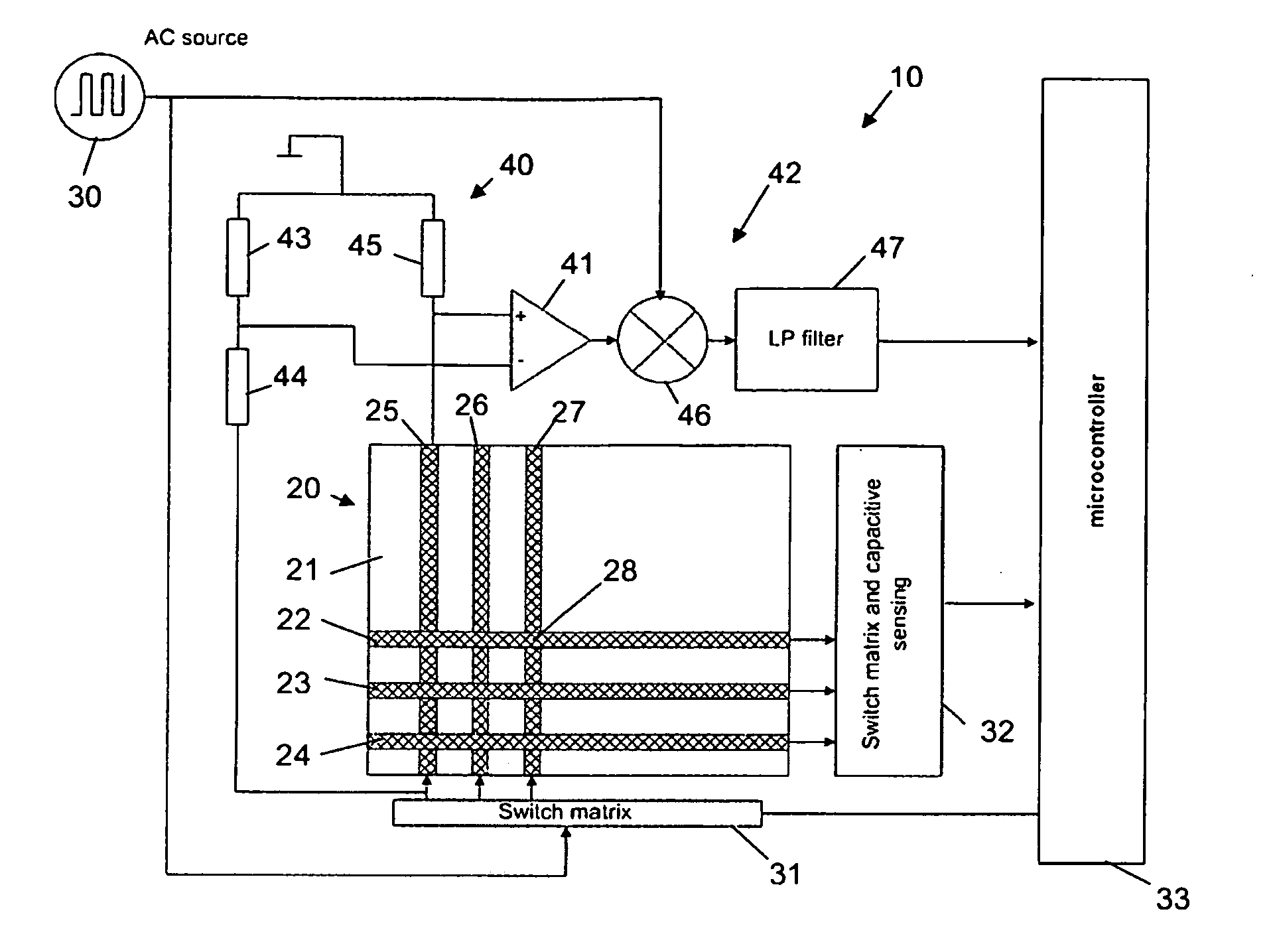
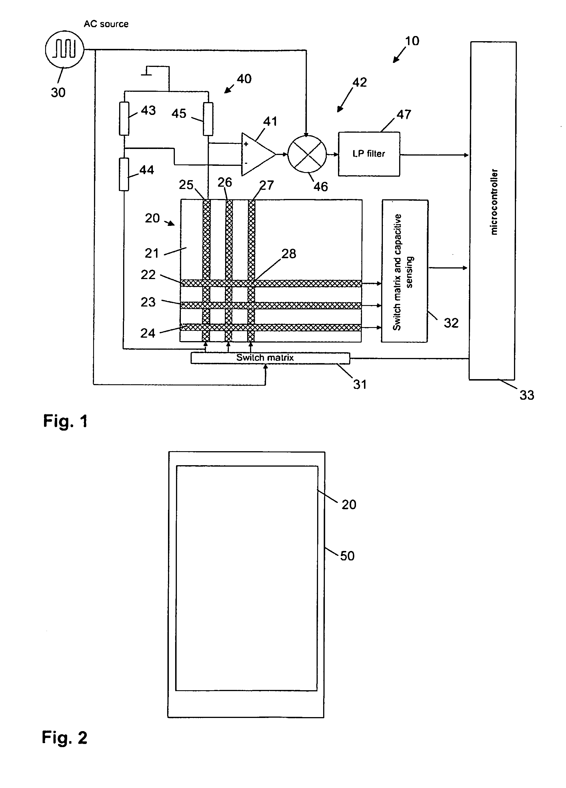
[0022]FIG. 1 shows a sensor arrangement 10 comprising a touch sensor 20 and a controller circuit for controlling the touch sensor 20.

[0023]The touch sensor 20 comprises a support layer 21 and an electrically conductive sensor structure 22-27 thereon. The support layer 21 may comprise for...


PUM


Abstract

The present invention relates to a method for controlling a touch sensor. The touch sensor comprises a support layer and an electrically conductive sensor structure thereon. The electrically conductive sensor structure forms a plurality of capacitors having a capacitance varying in response to a user touching or approaching the capacitor. The electrically conductive sensor structure comprises a piezoresistive material providing a resistance varying in response to a force being applied to the support layer. According to the method, an alternating electrical signal is supplied to the electrically conductive sensor structure for scanning the capacitors. An actuation position where the user touches the touch sensor is determined based on the alternating electrical signal and the capacitances of the capacitors. An electrical signal which is a function of the resistance of the electrically conductive sensor structure is detected and synchronously demodulated based on the alternating electrical signal.

Description

FIELD OF THE INVENTION[0001]The present application relates to a method for controlling a touch sensor, especially to a method for detecting an actuation position where the user touches or approaches the touch sensor and detecting a force being applied to the touch sensor. The present application relates furthermore to a controller for controlling a touch sensor, a sensor arrangement, and a device comprising the sensor arrangement.BACKGROUND OF THE INVENTION[0002]Touch sensors are known in the art for controlling devices, especially mobile or portable devices, via a user interface. The touch sensor may comprise a touch sensible panel which is arranged on top of a display forming a so-called touch screen. The touch screen provides a very intuitive way of operating the device. Information can be displayed on the display and in response to the displayed information the user may touch the display for initiating actions or operations. The touch sensor may work by detecting a change of ca...

Claims


Application Information

Patent Timeline
Patent Type & Authority Applications(United States)
IPC IPC(8): G06F3/044G06F3/045G06F1/16G06F3/041
CPCG06F3/044G06F3/0414G06F3/045G06F1/1643G06F3/0416G06F2203/04105G06F3/0446
Inventor KLINGHULT, GUNNAR
Owner SONY MOBILE COMM AB
Learn More