Sheet processing apparatus and image forming apparatus

a technology of image forming apparatus and sheet processing apparatus, which is applied in the direction of electrographic process, instruments, transportation and packaging, etc., can solve the problems of sheet bundle jumping out, costing to use staples as a whole,

Active Publication Date: 2015-01-01
CANON KK
View PDF8 Cites 17 Cited by
  • Summary
  • Abstract
  • Description
  • Claims
  • Application Information

AI Technical Summary

Benefits of technology

[0008]According to an aspect of the present invention, a sheet processing apparatus includes a sheet stacking portion on which sheets are stacked, a binding portion binding a plurality of sheets stacked on the sheet stacking portion as a bundle by deforming the sheets without a staple, a moving member moving the sheet bundle bound at a binding position by the binding portion from the binding position, and a restricting member restricting the move of the bound sheet bundle such that a distance between the bound sheet bundle and the moving member is kept to be less than a predetermined distance in moving the bound sheet bundle by the moving member.

Problems solved by technology

It is a cumbersome work to remove the staples from the sheet bundle, and the removed staples become waste, so that it is costly to use staples as a whole.
Therefore, there is a possibility that either one of the upper and lower teeth bites into the sheet, and the sheet may stick to the teeth if an engagement force of the upper and lower teeth is increased.
Then, while the sheet bundle is peeled off from either one of the upper and lower teeth and starts to move by being pushed by the press member, there is a possibility that the sheet bundle jumps out as the deflection caused in the sheet bundle is released at once.

Method used


Image

  • Sheet processing apparatus and image forming apparatus
  • Sheet processing apparatus and image forming apparatus
  • Sheet processing apparatus and image forming apparatus

Examples


first embodiment

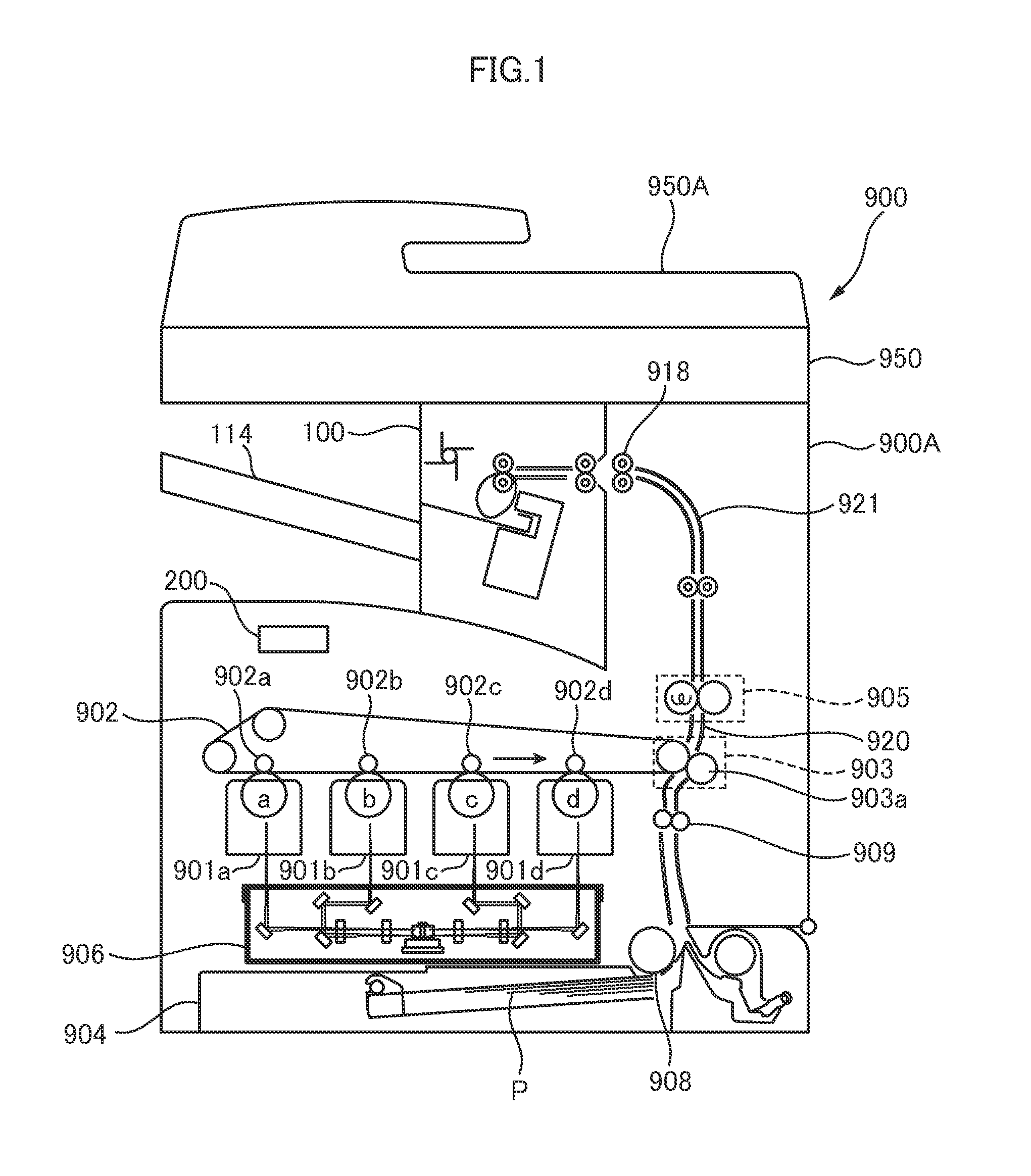
[0042]An image forming apparatus 900 of a first embodiment will be explained with reference to FIGS. 1 through 12. A schematic configuration of the image forming apparatus 900 will be explained at first with reference to FIG. 1. FIG. 1 is a schematic diagram showing a configuration of the image forming apparatus 900 of the first embodiment of the present invention.

[0043]As shown in FIG. 1, the image forming apparatus 900 includes a body of the image forming apparatus (referred to simply as an ‘apparatus body’ hereinafter) 900A configured to form an image on a sheet P, an image reading apparatus 950 capable of reading an image of a document, and a finisher 100, i.e., a sheet processing apparatus. In the present embodiment, the image reading apparatus 950 includes a document feeder 950A capable of automatically feeding a document, and the finisher 100 is disposed between an upper surface of the apparatus body 900A and the image reading apparatus 950.

[0044]The apparatus body 900A inclu...

second embodiment

[0089]Next, a second embodiment of the present invention will be explained with reference FIGS. 13 and 14. The second embodiment is different from the first embodiment in the drive control of the pair of aligning plates 109 made by the finisher control portion 220 after finishing the staple-less binding process. Therefore, the drive control of the pair of aligning plates 109 made by the finisher control portion 220 after finishing the staple-less binding process will be mainly explained and an explanation of the components and others of the image forming apparatus 900 will be omitted here. FIGS. 13A and 13B are schematic diagrams illustrating the staple-less binding job of the second embodiment, and FIG. 14 is a flowchart of the staple-less binding job of the second embodiment.

[0090]Because the processes from the selection of the staple-less binding job in the print job until when the staple-less binding job is executed are the same with those in the first embodiment, an explanation...

third embodiment

[0093]Next, a third embodiment of the present invention will be explained with reference FIGS. 15 and 16. The third embodiment is different from the first and second embodiments in the drive control of the pair of aligning plates 109 made by the finisher control portion 220 after finishing the staple-less binding process. Therefore, the drive control of the pair of aligning plates 109 made by the finisher control portion 220 after finishing the staple-less binding process will be mainly explained and an explanation of the components and others of the image forming apparatus 900 will be omitted here. It is noted that the processing tray 107 of the third embodiment is inclined downward in which the stacking surface is inclined downward in a direction of an arrow B as shown FIG. 15A. FIGS. 15A through 15D are schematic diagrams illustrating the staple-less binding job of the third embodiment, and FIG. 16 is a flowchart of the staple-less binding job of the third embodiment.

[0094]When t...


PUM

PropertyMeasurementUnit
distanceaaaaaaaaaa
widthaaaaaaaaaa
metallicaaaaaaaaaa

Abstract

A sheet processing apparatus includes a binding portion binding a plurality of sheets stacked on a sheet stacking portion as a bundle by deforming the sheets without a staple. The sheet processing apparatus further includes a moving member moving the sheet bundle bound at a binding position by the binding portion from the binding position and a restricting member restricting the move of the sheet bundle such that a distance between the sheet bundle and the moving member is kept to be less than a predetermined distance in moving the sheet bundle by the moving member.

Description

BACKGROUND OF THE INVENTION[0001]1. Field of the Invention[0002]The present invention relates to a sheet processing apparatus capable of binding a sheet bundle and an image forming apparatus including the same.[0003]2. Description of the Related Art[0004]Heretofore, there is known an image forming apparatus such as a copier, a printer, a facsimile, and a multi-function printer including a sheet processing apparatus configured to bind a plurality of sheets (sheet bundle) on which images have been formed. Many of the sheet processing apparatuses provided in the image forming apparatus is configured to bind a sheet bundle by using metallic staples. It is because the sheet processing apparatus using the metallic staples can bind the sheet bundle securely at a positioned specified by a user.[0005]However, the sheet bundle bound by the metallic staples necessitates the staples to be removed from the sheet bundle in putting through a shredder or in recycling the sheets. It is a cumbersome ...

Claims


Application Information

Patent Timeline
Patent Type & Authority Applications(United States)
IPC IPC(8): B42B5/00B65H31/34B65H43/04B65H9/06
CPCB42B5/00B65H43/04B65H31/34B65H9/06B65H37/04B31F1/07B31F5/02B31F2201/0754B65H9/04B65H2301/51616G03G2215/00852
Inventor ABE, HIDETO
Owner CANON KK
Why Eureka
Try Eureka