Eureka AIR delivers breakthrough ideas for toughest innovation challenges, trusted by R&D personnel around the world.

Method and apparatus for suppressing spurious values in a differential output current

Active Publication Date: 2005-12-20
SYNOPSYS INC
View PDF5 Cites 9 Cited by
  • Summary
  • Abstract
  • Description
  • Claims
  • Application Information

AI Technical Summary

Benefits of technology

[0010]Various means and methods have been described for reducing or eliminating spurious values in a differential output signal.
[0013]Various embodiments of the present invention may have one or more of the following advantages.
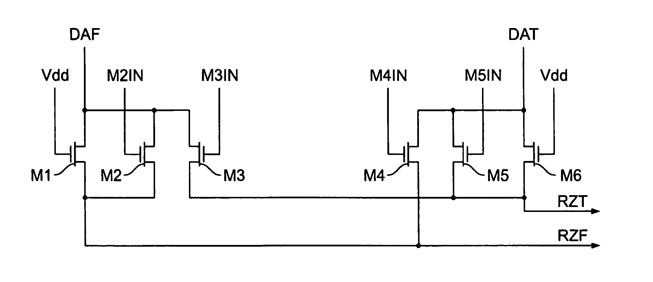
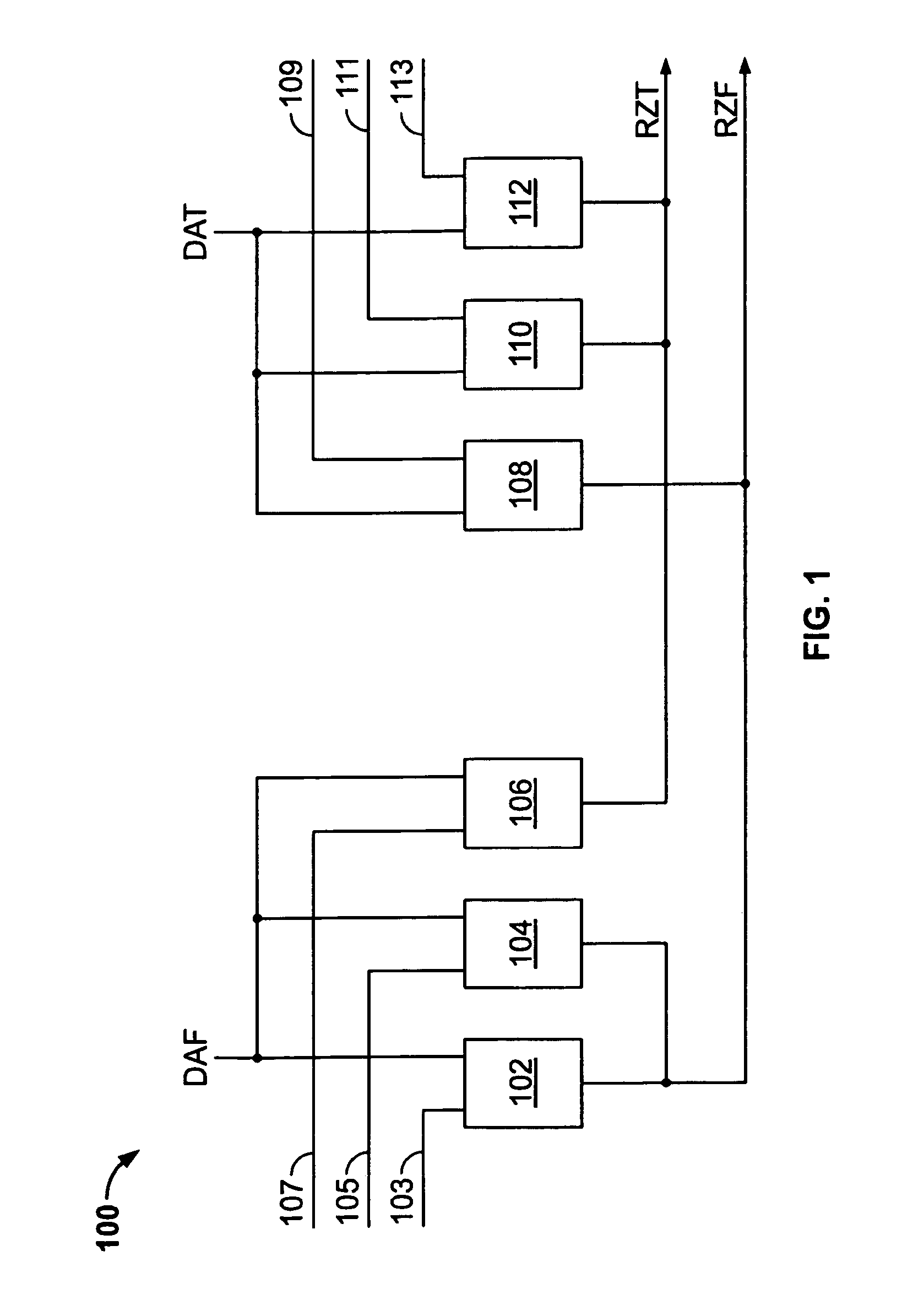
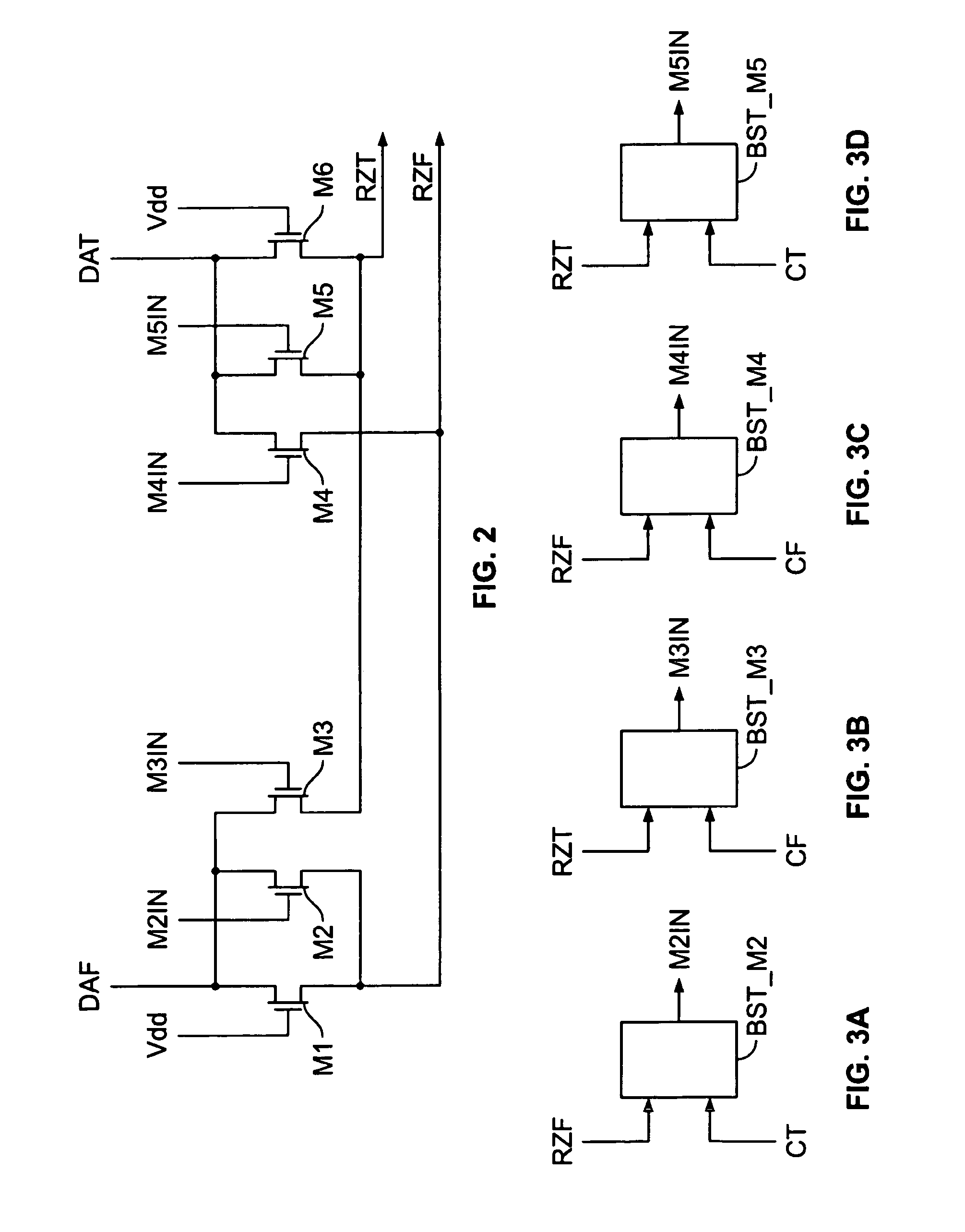
[0014]Prior art implementations have used track-and-attenuate methods, whereby the differential output currents are effectively shorted to ground using a FET during the zero phase and released during the track phase. As compared to the “track-attenuate” method, mentioned above, embodiments of the present invention have the advantage of setting the RZT and RZF output currents to the middle of their range during the zero phase, rather than to ground. Thus, on average, the RZT and RZF output currents will have less “current distance” to travel on any particular phase transition (i.e., whether zero-to-tracking or tracking-to-zero), and will therefore adjust more quickly. The quicker adjustment times mean fewer and briefer transient anomalies, which in turn enables faster clock speeds.
[0015]Compared to the conventional “track-attenuate” approach, embodiments of the present invention have the advantage of setting the differential output current of the RZ circuit to zero during the zero phase, instead of just attenuating the differential input. This has the effect of substantially reducing, or completely eliminating, spurious output during the zero phase.

Problems solved by technology

While the aforementioned advances have done much for the rapid advancement of digital systems, those advances do not necessarily translate into equally impressive gains in the performance of analog circuits.
Analog waveforms produced by electronic circuits, for example those generated by a digital-to-analog converter (DAC), often exhibit spurious features, such as transients or ringing.

Method used


Image

  • Method and apparatus for suppressing spurious values in a differential output current
  • Method and apparatus for suppressing spurious values in a differential output current
  • Method and apparatus for suppressing spurious values in a differential output current

Examples


Embodiment Construction

[0019]Analog waveforms produced by electronic circuits, for example those generated by a digital-to-analog converter (DAC), often exhibit spurious features, such as transients or ringing. Various embodiments of the present invention provide methods and apparatus for producing cleaner analog waveforms that more truly reflect their ideal values.

[0020]Reference herein to “one embodiment”, “an embodiment”, or similar formulations, means that a particular feature, structure, operation, or characteristic described in connection with the embodiment, is included in at least one embodiment of the present invention. Thus, the appearances of such phrases or formulations herein are not necessarily all referring to the same embodiment. Furthermore, various particular features, structures, operations, or characteristics may be combined in any suitable manner in one or more embodiments.

[0021]The terms, chip, integrated circuit, monolithic device, semiconductor device, and microelectronic device, a...


PUM


Abstract

Methods and apparatus provide for front-end processing of a first differential output current, whereby a first differential output current is received and a second differential output current having reduced spurious content is produced. Current steering is used to divide, and reassemble, the first differential output current so as to provide an output signal with reduced spurious content. Current steering is implemented by a return-to-zero circuit that is coupled to the terminals of a first differential current output stage. During a first phase, the return-to-zero circuit provides a differential output current equal to the first differential current output. During a second phase, the return-to-zero circuit provides a differential output current equal to zero. The current steering return-to-zero circuit is implemented with MOSFETs or any other suitable electrical circuit element that provides the ability to controllably pass or refrain from passing current.

Description

CROSS REFERENCE TO RELATED APPLICATION[0001]This application claims the benefit of U.S. provisional application No. 60 / 388,782, filed Jun. 13, 2002.FIELD OF THE INVENTION[0002]The methods and apparatus of the present invention relate generally to electronic circuits, and more particularly to circuits and operations that suppress spurious values in the currents of a differential output circuit.RELATED ART[0003]Advances in semiconductor manufacturing technology, as well as in computer and communication systems architectures, have resulted in demand for electronic systems with higher operating speeds, and higher frequency signals. Smaller feature sizes for circuit elements, such as transistors, as well as smaller interconnect pitches, generally produce faster digital circuits. Such reductions in the feature sizes have also resulted in the demand for higher levels of circuit integration, including the fabrication of Systems on Chip (SoC).[0004]It is often desirable to form integrated ci...

Claims


Application Information

Patent Timeline
IPC IPC(8): H03K19/003H03K19/0175H03K19/094
CPCH03K19/00361
Inventor HYDE, JOHN D.
Owner SYNOPSYS INC
Why Eureka
Eureka Blog
Learn More