
High dynamic range reading circuit based on backside illuminated image sensor

An image sensor and high dynamic range technology, applied in image communication, television, electrical components, etc., can solve the problems of pixel signal accuracy reduction, multiple power consumption, and consumption, so as to improve dynamic range, reduce quantization error, and improve signal quality. The effect of the noise ratio

Active Publication Date: 2020-08-18
XI AN JIAOTONG UNIV
View PDF6 Cites 7 Cited by
  • Summary
  • Abstract
  • Description
  • Claims
  • Application Information

AI Technical Summary

Problems solved by technology

This type of structure generally works at a low rate, on the order of hundreds of kHz, and the accuracy is not high, and the number of bits is 8 to 12 bits; however, when the number of ADC bits exceeds 12 bits or the clock speed reaches the order of hundreds of MHz, the integral ADC It is difficult to achieve both power consumption and area, resulting in a decrease in the signal accuracy of pixel readout
[0005] Therefore, the dynamic range of the traditional readout circuit is limited, and the clock speed needs to be continuously increased to make up for the defects of the progressive exposure method, but the high-speed comparator, amplifier and other circuits will consume more power consumption

Method used


Image

  • High dynamic range reading circuit based on backside illuminated image sensor
  • High dynamic range reading circuit based on backside illuminated image sensor
  • High dynamic range reading circuit based on backside illuminated image sensor

Examples


Embodiment Construction

[0043] In the description of the present invention, it should be noted that unless otherwise specified and limited, the terms "installation", "connection" and "connection" should be understood in a broad sense, for example, it can be a fixed connection or a detachable connection. Connected, or integrally connected; it can be mechanically connected or electrically connected; it can be directly connected or indirectly connected through an intermediary, and it can be the internal communication of two components. Those of ordinary skill in the art can understand the specific meanings of the above terms in the present invention in specific situations.

[0044] Various structural schematic diagrams according to the disclosed embodiments of the present invention are shown in the accompanying drawings. The figures are not drawn to scale, with certain details exaggerated and possibly omitted for clarity of presentation. The shapes of various regions and layers shown in the figure and ...


PUM


Abstract

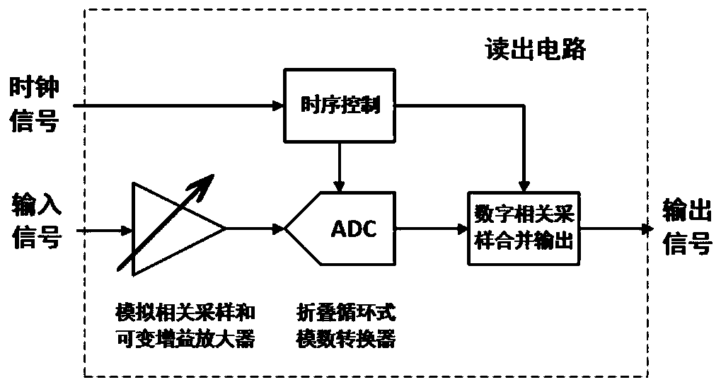
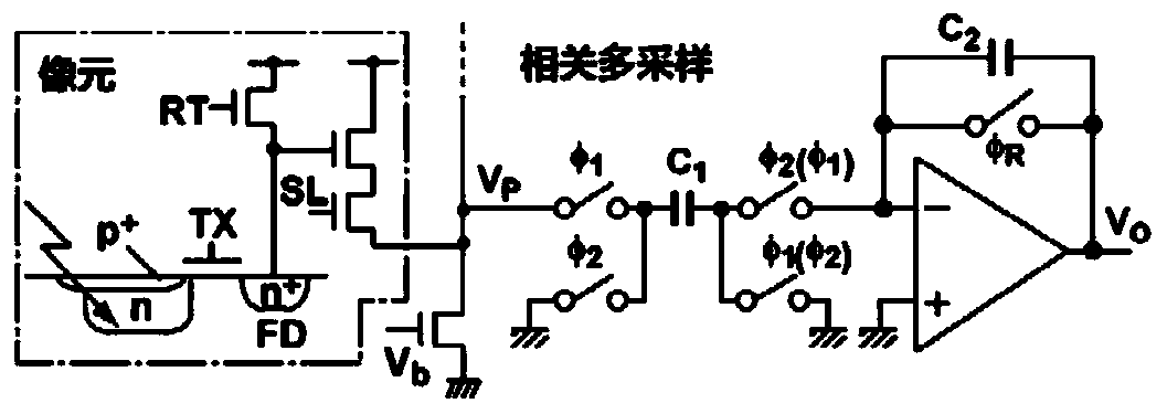
The invention discloses a high dynamic range reading circuit based on a backside illuminated image sensor, which comprises an analog correlation sampling and programmable gain amplifier, and is characterized in that a voltage signal read from a pixel is amplified and then transmitted to a lower-level analog-to-digital converter through a switch switching strategy of multiple times of sampling andholding and adjustment to a set gain; the folding circulating analog-to-digital converter is used for quantizing the signals subjected to preceding-stage preventive large sampling; the digital correlation sampling merging logic circuit is used for obtaining a real digital quantized signal; the time sequence control circuit is used for controlling the analog-to-digital converters in each column line by line; an input signal sequentially passes through the analog correlation sampling and programmable gain amplifier, the folding circulation type analog-to-digital converter and the digital correlation sampling merging logic circuit and then outputs a quantized signal, and a clock signal passes through the sequential control circuit and then is input into the folding circulation type analog-to-digital converter and the digital correlation sampling merging logic circuit. Quantization errors are reduced, the dynamic range is enlarged, and the overall power consumption and area of the readingcircuit are reduced.

Description

technical field [0001] The invention belongs to the technical field of low-power integrated circuits, in particular to a high dynamic range readout circuit based on a back-illuminated image sensor, and relates to the fields of bionic navigation, target detection and other embedded systems and consumer electronics products. Background technique [0002] With the continuous advancement of technology and the continuous improvement of people's living standards, consumer-grade digital cameras, portable smart phones and other imaging equipment have become necessities. The collection and processing of image information plays an important role in various fields such as consumption, medical treatment, security and aerospace. Therefore, new requirements such as low power consumption, high dynamic range, and high speed are put forward for the readout circuit of the image sensor. [0003] In the readout circuits used in bionic navigation and target detection systems, with the improveme...

Claims


Application Information

Patent Timeline
Patent Type & Authority Applications(China)
IPC IPC(8): H04N5/378
CPCH04N25/75H04N25/616H04N25/618
Inventor 耿莉何程扬张冰辛有泽赵泽亮
Owner XI AN JIAOTONG UNIV
Learn More