Electromagnetic moving system

a moving system and electromagnetic technology, applied in the direction of propulsion systems, generators/motors, electrical apparatus construction details, etc., can solve the problems of large power consumption, difficult to provide reliable smooth speedy motion to such moving bodies, etc., and achieve the effect of less power and less distan

Inactive Publication Date: 2009-11-24
INDAL DESIGN LAB
View PDF29 Cites 9 Cited by
  • Summary
  • Abstract
  • Description
  • Claims
  • Application Information

AI Technical Summary

Benefits of technology

[0009]The general idea of the claimed invention is that the spirals of one layer are shifted in respect to the spirals of the adjacent layer along the line connecting the center points in such a way thus the center points of the spirals of one layer in transparent view are located between two nearest spirals of the adjacent layer. This specific feature in the stator design provides less distance between the coil windings magnetic poles thus require less power to achieve smooth motion with minimal attraction. According to this the claimed invention is characterized by being more efficient in comparison with known designs, operating under equal conditions.

Problems solved by technology

The main problem with all such known devices is that it is difficult to provide reliable smooth speedy motion to such moving bodies because of the relative large distance between the magnetic poles.
Such magnetic poles configuration requires increasing alternative forces to achieve enough attraction and tending to propel the moving body and needs much more power.

Method used


Image

  • Electromagnetic moving system
  • Electromagnetic moving system
  • Electromagnetic moving system

Examples


first embodiment

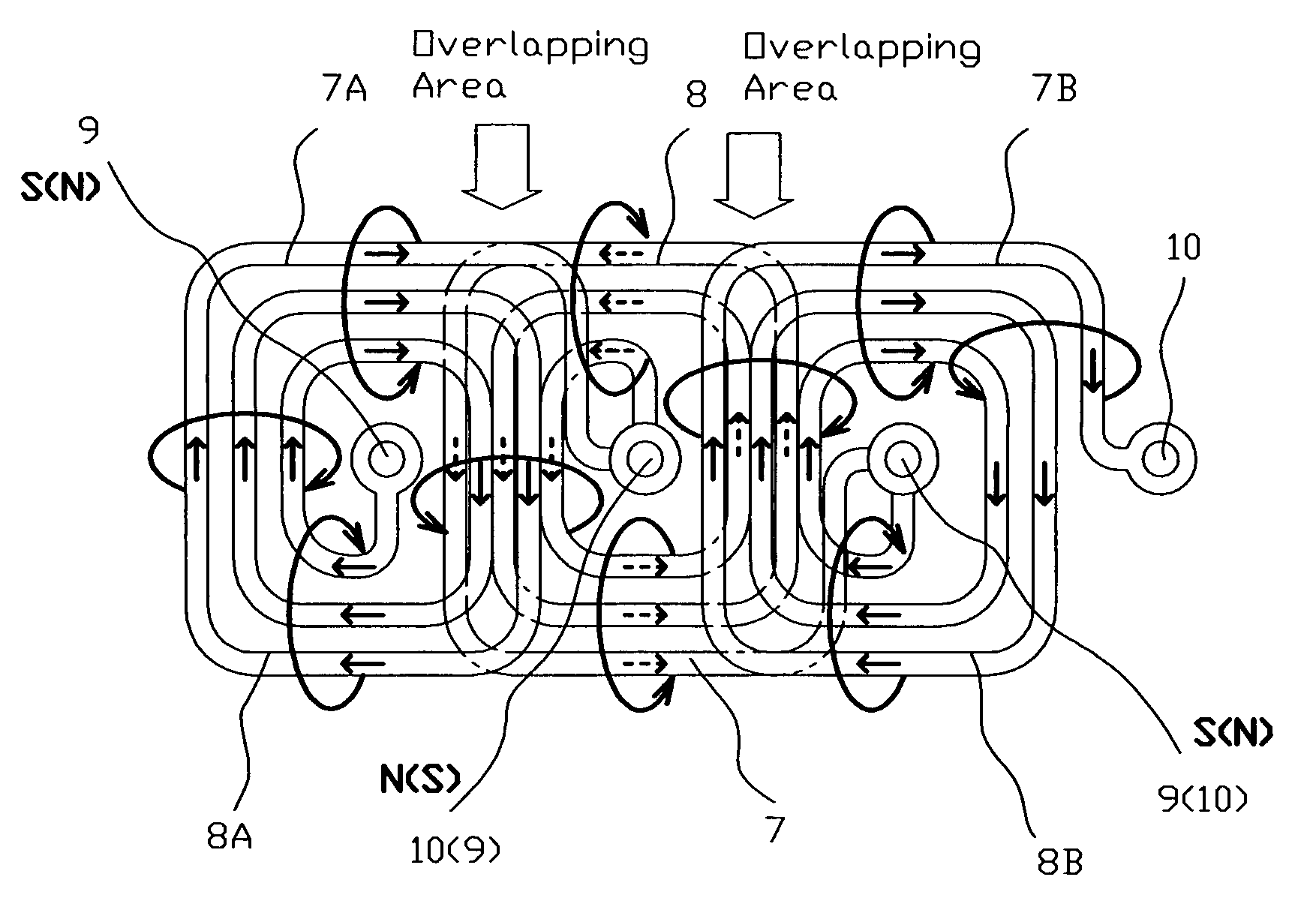
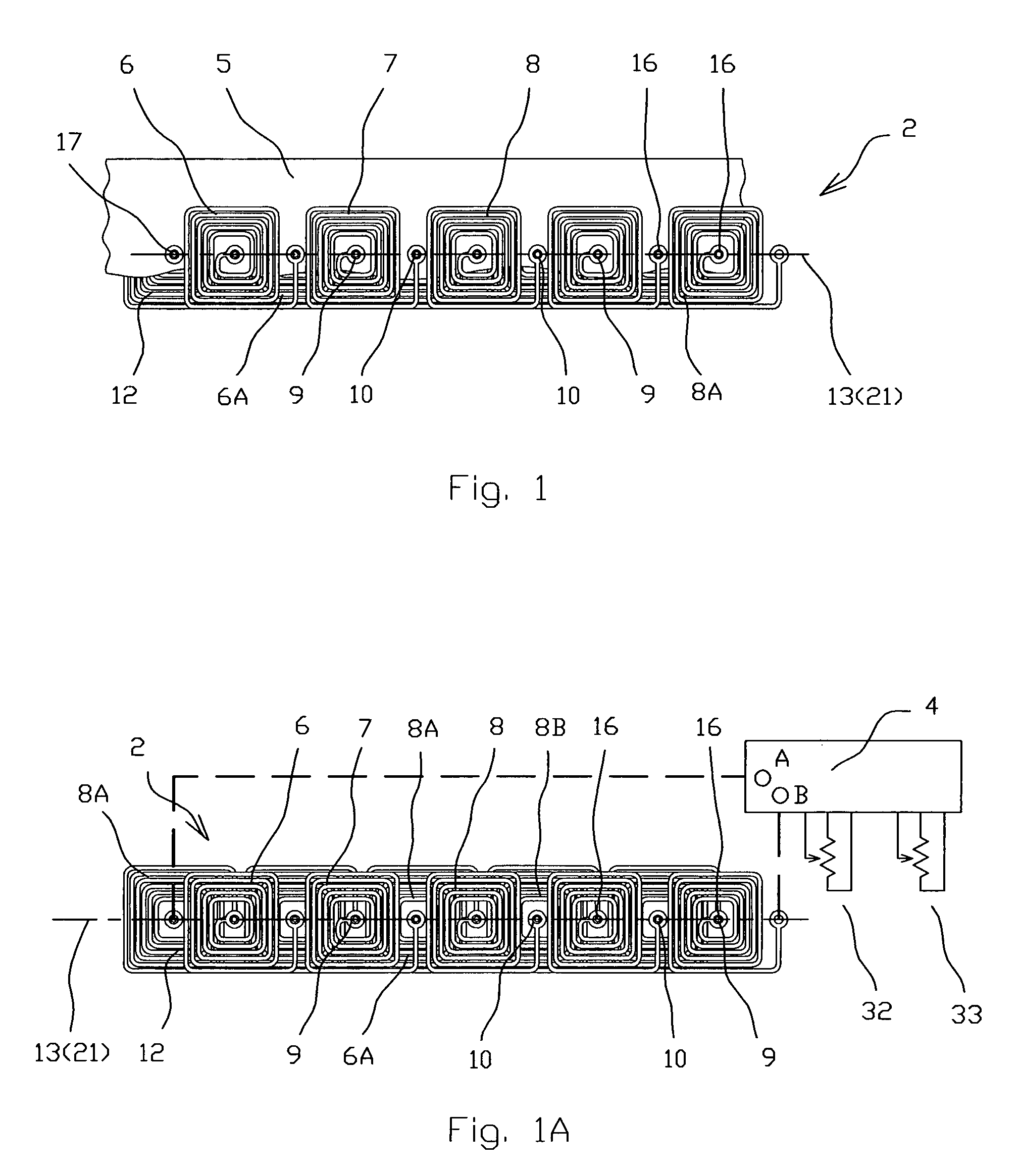
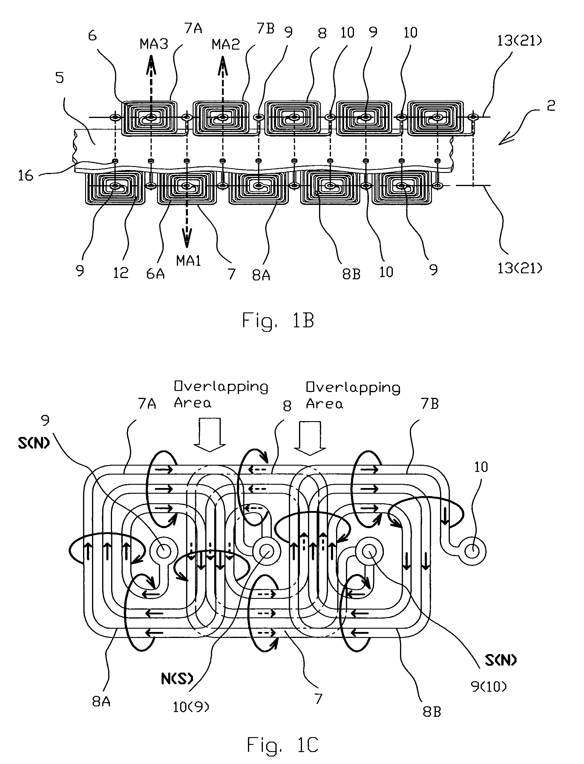
[0041]According to the present invention (FIGS. 1-1B), the spirals 8 are identical and the center point 9 of each of the spirals 8 of one layer 6 is electrically connected through the circuit board 5 by internal via's 16, which is a copper plated hole 17, with the peripheral point 10 of the nearest spiral 8 of the adjacent layer 6A, while the peripheral point 10 of each of the spirals 8 of one layer 6 is electrically connected by the via's 16 with the central point 9 of the another nearest spiral 8 of the adjacent layer 6A thus the stator 2 serves as a single phase stator.

[0042]The stator 2 is incorporated with a track 19 with a contact surface 20, and the moving body 3 located on the contact surface 20, and the line connected the center points 9 of the spirals 8 is an assembly of straight 21 and curved 22 lines connecting in a series way, thus the system 1 serves as a linear electric drive (FIGS. 8 and 8A). The line connecting the center points 9 of the spirals 8 may form a close l...

second embodiment

[0044]There is the present invention (FIGS. 2-2B). The spirals 8 are identical and the center point 9 of each of the spirals 8 of one layer 6 is electrically connected through the circuit board 5 by internal via's 16, which is a copper plated hole 17, with the peripheral point 10 of the spiral 8C following next of the nearest spiral 8A of the adjacent layer 6A, while the peripheral point 10 of each of the spirals 8 of one layer 6 is electrically connected by the via's 16 with the central point 9 of the spiral 8D following next of the another nearest spiral 8B of the adjacent layer 6A thus the stator 2 serves as a three-phase stator.

[0045]The stator 2 of the electromagnetic moving system 1 according to the second embodiment operates in the following ways. When electrical power is supplied from the power source (not shown) through the connectors A, B and C of the controller 4 to the coils windings 7 of the layers 6 and 6A that operate together as the stator 2 (FIG. 2A), alternating el...

third embodiment

[0046]According to the present invention, each two adjacent spirals 8 and 8E of each layer 6 are oriented opposite one to one and coupled in pair 18 with the mutual peripheral points. Each of the center points 9 of each of the pairs 18 of each layer 6 are electrically connected with the nearest center points 9 of the adjacent pairs 18A and 18B of the same layer 6 by the jumpers 35 and 35A located at the adjacent layer 6A, thus said stator 2 servers as a two-phase stator.

[0047]The stator 2 of the electromagnetic moving system 1 according to the third embodiment operates in the following ways. When electrical power is supplied from the power source (not shown) through the connectors A, B and C of the controller 4 to the coils windings 7 of the layers 6 and 6A that operate together as the stator 2 (FIG. 3A), alternating electromagnetic fields are created and controlled by the speed 32 and voltage 33 regulators.


PUM

PropertyMeasurementUnit
current flowaaaaaaaaaa
magnetic axisaaaaaaaaaa
transparentaaaaaaaaaa

Abstract

An electromagnetic moving system comprises a stator, a moving body and a controller. The stator comprises a circuit board with two layers of electrically connected coil windings spaced apart in a series way and made as spirals with center and peripheral points. The spirals of one layer are shifted in respect to the spirals of the adjacent layer along the line connecting the center points thus the center points of the spirals of one layer in transparent view are located between two nearest spirals of the adjacent layer. Each of the spirals of one layer in transparent view at least partially overlaps two nearest spirals of the adjacent layer. The moving body is comprised of one permanent magnet such as to cause interaction with the stator when it is powered, thus creating a force tending to propel the moving body along the line connecting said center points.

Description

FIELD OF THE INVENTION[0001]The present invention relates generally to electromagnetic systems for moving mechanical bodies along predefined linear and / or curved ways. More particularly, the present invention relates to toy and / or entertainment systems, and all subsystems in which are useful to controllably move an object upon a surface. The present invention is particularly, but not exclusively, useful for systems that relates to toy motion devices like trains and railway vehicles.[0002]At the same time the present invention may be relate to some types of blowers for cooling of electronic devices and be useful for cooling systems for regulating the temperature of electronic components of blade servers.BACKGROUND OF THE INVENTION[0003]There are known electromagnetic moving systems that include a stator made as one layer circuit board, and at least one body moving along the way defined by the stator configuration. For example, the GB Patent No 979985 “Improvements in or relating to E...

Claims


Application Information

Patent Timeline
Patent Type & Authority Patents(United States)
IPC IPC(8): H01F5/00H02K41/00
CPCA63H18/10H02K41/03A63H18/14A63H18/12Y10S310/06
Inventor LOPATINSKY, EDWARDFEDOSEYEV, LEVSCHAEFER, DANIEL
Owner INDAL DESIGN LAB
Why Eureka
Try Eureka