Linear shaped charge

a linear charge and charge technology, applied in the field of linear charge, can solve the problems of increased cutting width, spall fracture, reduced penetration depth of target wounds, etc., and achieve the effect of effective cutting jet, excellent cutting efficiency, and improved jet quality

Active Publication Date: 2013-01-17
JET PHYSICS
View PDF16 Cites 12 Cited by
  • Summary
  • Abstract
  • Description
  • Claims
  • Application Information

AI Technical Summary

Benefits of technology

[0014]A linear shaped charge designed in accordance with these parameters still allows the explosive load of the charge to be selected in accordance with the intended cutting task.
[0015]In yet further embodiments, a length L of a side of the V-shaped liner furthest from the face is 8.1 T to 9.9 T milli-metres, 8.55 T to 9.45 T milli-metres, or 9 T milli-metres. Further, a thickness E of the explosive element, taken perpendicular a length of a side of the V-shaped explosive element, may be 4.5 T to 5.5 T milli-metres, 4.75 T to 5.25 T milli-metres, or 5 T milli-metres. Moreover, the thickness T may be 0.9 to 1.1 milli-metres, 0.95 to 1.05 milli-metres or 1 milli-metre. In other embodiments, the thickness T may be 0.4 to 6.1, 0.4 to 0.5, 0.5, 0.7 to 0.9, 0.8, 1.3 to 1.6, 1.5, 1.7 to 2.1, 1.9, 2.4 to 2.9, 2.6, 3.8 to 4.7, 4.3, 4.4 to 5.4, 4.9, 5.0 to 6.1 or 5.5 milli-metres. Linear shaped charges designed in accordance with a length L, thickness E and thickness T dimensions selected from those above exhibit excellent cutting efficiency. Selecting at least one of the length L, thickness E and thickness T dimensions in accordance with the above, for a linear shaped charge having an apex angle and stand-off dist...

Problems solved by technology

In prior art situations the cutting jet may break up, losing its homogeneity; accordingly, the quality of the target cut su...

Method used


Image

  • Linear shaped charge
  • Linear shaped charge

Examples


Embodiment Construction

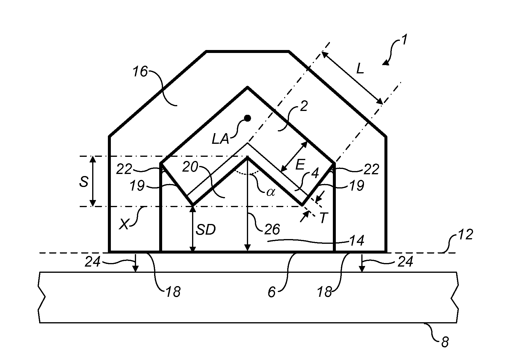
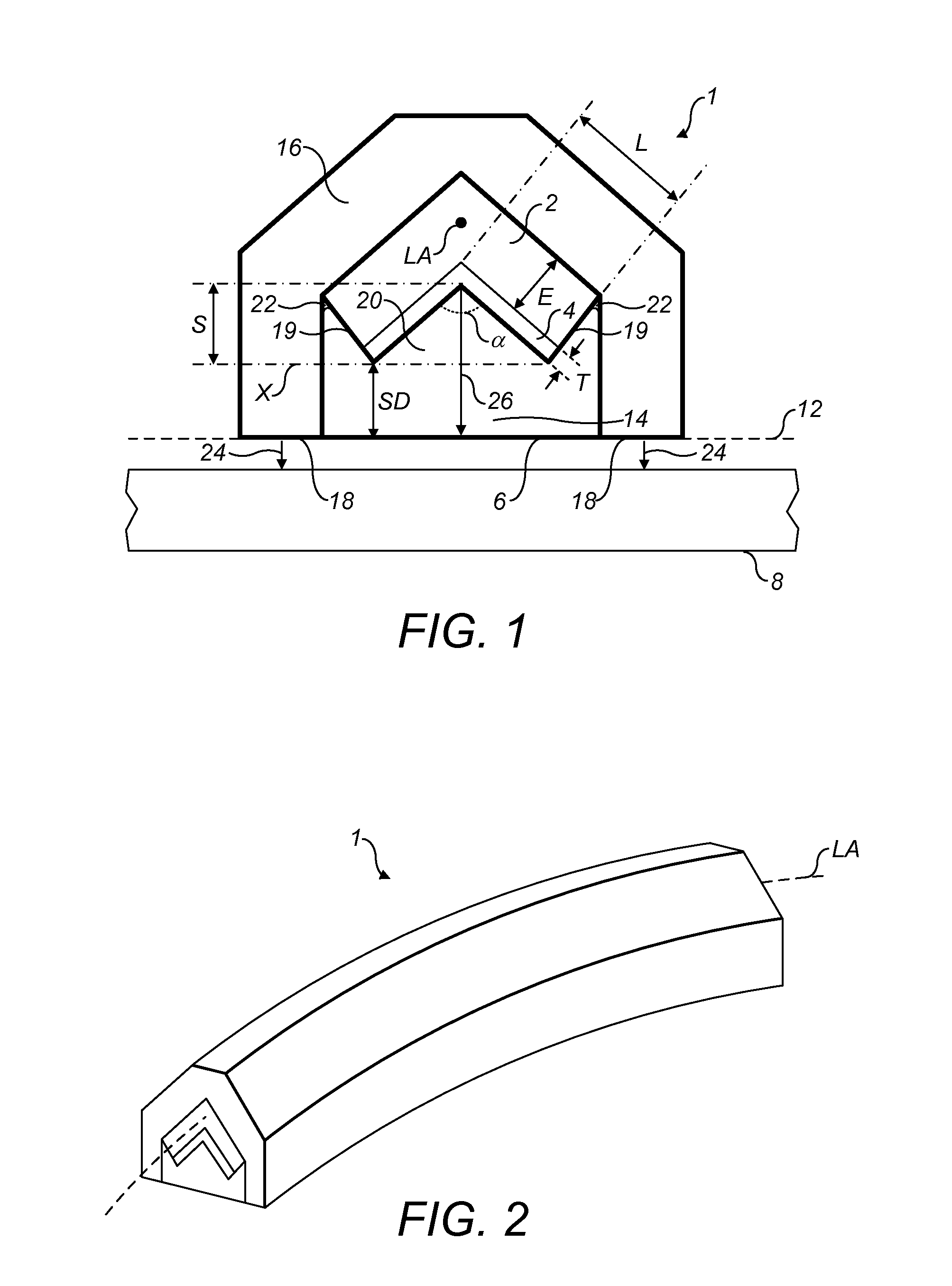
[0024]FIG. 1 shows schematically a cross section of a linear shaped charge 1 according to an embodiment of the present invention. FIG. 2 shows schematically a perspective view of the linear shaped charge 1 of this embodiment.

[0025]Referring to FIG. 1, the linear shaped charge comprises an explosive element 2, a liner 4, and a face 6 for application to a target object 8. The explosive element and the liner have a V-shaped cross section, taken in a plane perpendicular a longitudinal axis LA of the charge 1, as illustrated in FIG. 1. The term V-shape includes forms where the two sides of the V, either side of the apex, are equal, or unequal, in length; the sides may be equal. The liner lies in a groove of the V shaped cross section of the explosive element. The explosive element and the liner are formed of materials which adhere to each other upon contact, without requiring a separate adhesive. The face 6 is planar, defining a target plane 12. There is a space 14 between the liner 4 an...


PUM


Abstract

One or more aspects of the present invention relate to a linear shaped charge comprising an explosive element, a liner, a face for application to a target object and a space between the liner and the face, the liner being arranged for projection through the space, towards the face, when the explosive element is detonated, and the explosive element and the liner having a V-shaped cross section, the liner lying in a groove of the V-shaped cross section of the explosive element, the liner having a length L of a side furthest from the face and the liner having a thickness T taken perpendicular to said length L, wherein an angle α of an apex of the liner nearest the face is 101.5 to 106.5 degrees, and a stand-off distance SD between the face and a point of the liner nearest the face is 0.99 S to 1.21 S, S being a distance, parallel the stand-off distance SD, between the point of the liner nearest the face and the apex of the liner nearest the face.

Description

CROSS-REFERENCE TO RELATED APPLICATIONS[0001]This application is a Continuation of PCT / GB2011 / 000062, filed Jan. 18, 2011 which is an international application claiming priority to Great Britain App. No. 1000850.6, filed Jan. 18, 2010. The entire contents of which are incorporated herein by reference in their entirety.FIELD OF THE INVENTION[0002]The present invention relates to a linear shaped charge.BACKGROUND OF THE INVENTION[0003]A linear cutting charge is an explosive device for cutting a target object. A type of linear cutting charge is termed a linear shaped charge. Linear shaped charges are known from the prior art, for example from U.S. Pat. No. 4,693,181, and the product commercially known as “Blade”® generic charge, demolition, linear, cutting / flexible, lightweight (CDLC / FL). In use, a linear shaped charge is applied to a target object for cutting. Upon detonation of an explosive element in the charge, a metal liner forms a metal slug which is projected as a cutting jet to...

Claims


Application Information

Patent Timeline
IPC IPC(8): F42B1/028C10B49/10C10J3/46
CPCC10B49/10F42B1/028C10J2300/0933
Inventor LUMLEY, ANDREW
Owner JET PHYSICS
Why Eureka
Try Eureka