Vibration damping device

a vibration damping and vibration technology, applied in shock absorbers, gearings, fluid couplings, etc., can solve the problems of degrading durability and noise generation of rotary members, and achieve the effects of reducing vibration, enhancing the vibration damping effect of the oscillating motion of the rolling member, and reducing vibration

Active Publication Date: 2015-01-01
TOYOTA JIDOSHA KK
View PDF13 Cites 25 Cited by
  • Summary
  • Abstract
  • Description
  • Claims
  • Application Information

AI Technical Summary

Benefits of technology

[0012]Thus, the vibration damping device of the present invention reduce vibrations resulting from a pulsation of torque applied to a rotary member by an oscillating motion of a rolling member connected with the rotary member while being allowed to rotate relatively therewith. According to the present invention, the rolling member is held in the casing member connected with the rotary member though the sealing member while being allowed to rotate relatively, and preventing oil from entering into an inner space of the casing member. Therefore, number of oscillation per rotation of the rolling member will not be changed by viscosity resistance of the oil. That is, vibration damping effect of the vibration damping device will not be degraded by the oil.
[0013]As described, the casing member is connected with the rotary member while being allowed to rotate relatively therewith. Therefore, in addition to the above-mentioned advantages, a mass of the casing member is not added to a mass of a member rotated together with the rotary member whose vibrations are damped by the oscillating motion of the rolling member. That is, the mass of the rolling member can be increased relatively with respect to the mass of the rotary member whose vibration is damped by the oscillating motion of the rolling member. For this reason, the vibration damping effect of the oscillating motion of the rolling member can be enhanced.
[0014]As also described, the vibration damping device of the present invention is further provided with the elastic member for reducing a phase shift between the rotary member and the casing member rotating relatively with each other so that the casing member is allowed to serve as a mass damper. Therefore, the casing member is allowed to contribute to damp the vibrations of the rotary member.

Problems solved by technology

As a result, noise is generated and durability of the rotary member is degraded.

Method used


Image

  • Vibration damping device
  • Vibration damping device
  • Vibration damping device

Examples


Embodiment Construction

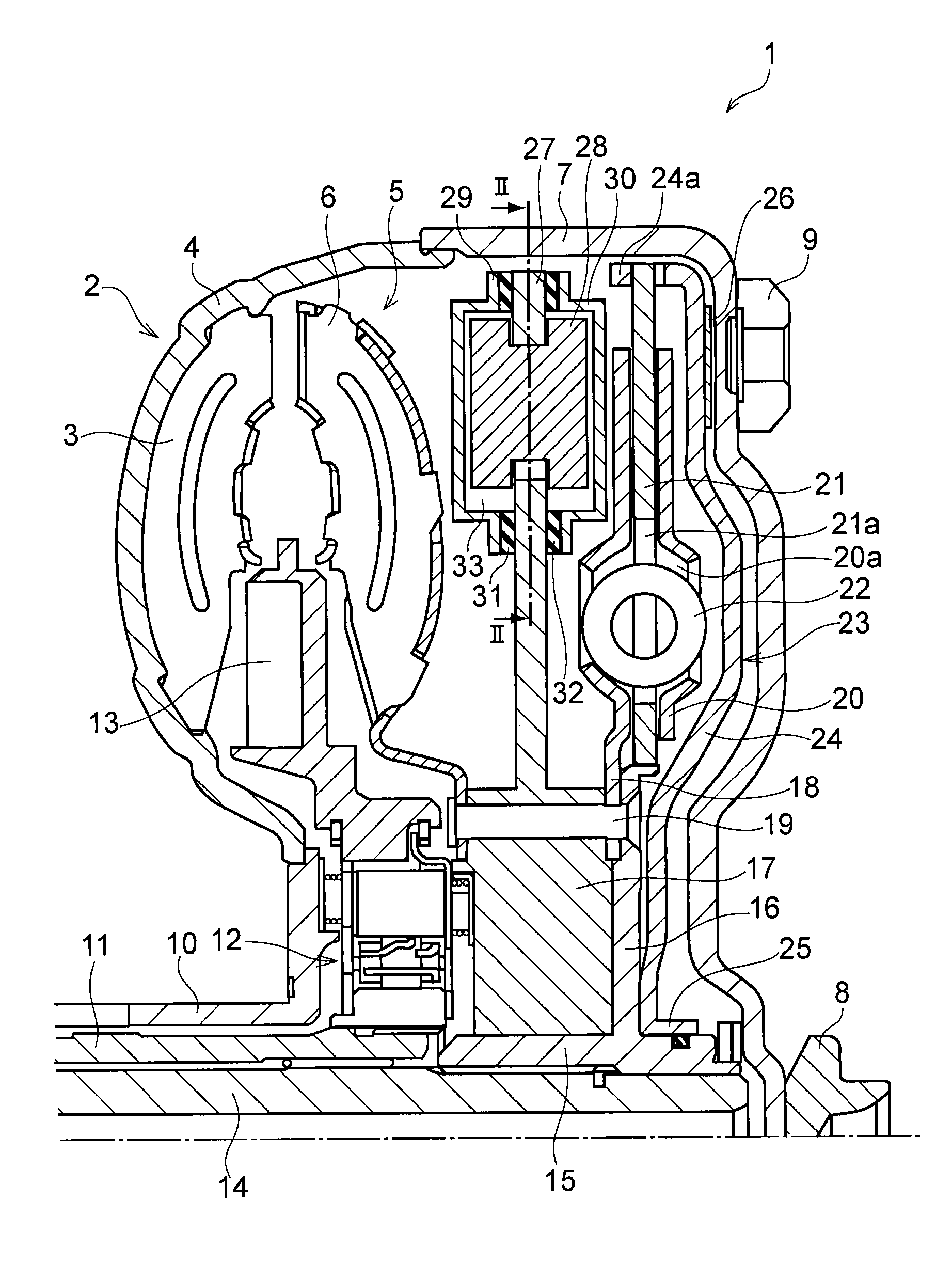
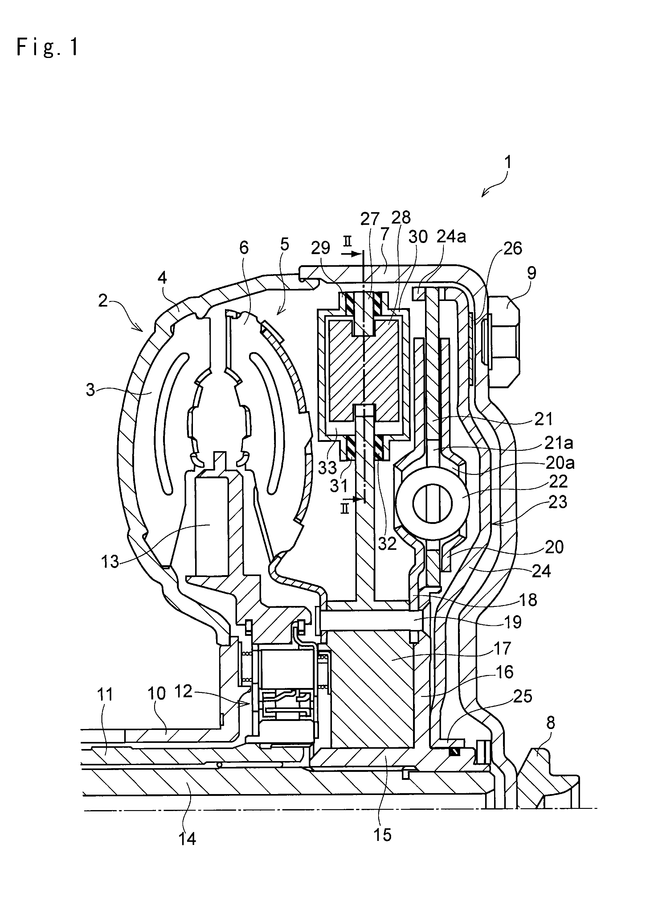
[0019]Next, a preferred example of the vibration damping device of the present invention will be explained in more detail. Referring now to FIG. 1, there is shown an example in which the vibration damping device is arranged in a torque converter 1 as a hydraulic transmission adapted to amplify a torque. The torque converter 1 shown therein is structured as a conventional torque converter widely used in vehicles. Specifically, a plurality of pump blades 3 is arranged radially on an inner face of a pump shell 4 of a pump impeller 2 as an input side member, and a turbine runner 5 serving as the driven side member of the present invention is arranged to be opposed the pump impeller 2. A configuration of the turbine runner 5 is substantially symmetrically with that of the pump impeller 2, and a plurality of turbine blades 6 is arranged radially on an inner face of an annular (or semitorus-shape) shell. Thus, the pump impeller 2 and the turbine runner 5 are arranged coaxially while being ...


PUM


Abstract

A vibration damping device in which vibration damping performance of a damper having a chamber holding a rolling member is improved. The vibration damping device is adapted to damp vibrations resulting from a pulsation of torque applied to a rotary member by an oscillating motion of a rolling member connected with the rotary member while being allowed to rotate relatively therewith. The vibration damping device is provided with a casing member enclosing the rolling member, and a sealing member that connects the casing member with the rotary member in a manner such that the rotary member is allowed to rotate relatively with the casing member, while preventing oil from entering into an inner space of the casing member where the rolling member is held to oscillate.

Description

TECHNICAL FIELD[0001]This invention relates to a vibration damping device for reducing torsional vibrations, and especially to a vibration damping device comprising a rotary member rotated by torque and a rolling member held in the rotary member while being allowed to rotate relatively with the rotary member.BACKGROUND ART[0002]A rotary member such as a drive shaft, a gear and so on used to transmit a torque from a prime mover to a desired portion or a member is vibrated inevitably by a pulsation of the torque or load, or by a friction. A frequency of the vibration is varied according to rotational speed, and high order vibrations such as secondary vibrations are also generated. Therefore, amplitude of vibrations is widened by resonance. As a result, noise is generated and durability of the rotary member is degraded. An example of a device or mechanism for suppressing such vibrations of equipment for transmitting power by rotation is disclosed in Japanese Patent Laid-Open No. 2011-5...

Claims


Application Information

Patent Timeline
Patent Type & Authority Applications(United States)
IPC IPC(8): F16F9/32F16F15/121
CPCF16F15/121F16F9/3207F16H45/02F16H2045/0205F16F15/145F16F15/173F16H2045/0242F16H2045/0294F16H2045/0263F16F15/12353
Inventor SEKIGUCHI, TADASHIAMANO, HIROYUKI
Owner TOYOTA JIDOSHA KK
Why Eureka
Try Eureka