
Shaking and centrifuging device

a technology of shaking and centrifuging, which is applied in the direction of centrifuges, centrifuge sediment separation, mixers, etc., can solve the problems of reducing the wait time between the two centrifuging modes, limiting the speed of each of the centrifuges, and reducing the risk of error, so as to achieve simple implementation and free of possible errors

Inactive Publication Date: 2015-01-01
CHOPIN TECH
View PDF38 Cites 15 Cited by
  • Summary
  • Abstract
  • Description
  • Claims
  • Application Information

AI Technical Summary

Benefits of technology

The patent describes a way to shake and centrifuge samples to make testing easier and more accurate. This method ensures that the shaking and centrifuging parameters are always correct, and can be quickly switched between. The technical effect of this invention is to provide a more reliable and efficient way to conduct testing on samples.

Problems solved by technology

Furthermore, with this device the wait time between the two centrifuging modes is reduced and possible errors in placement of the samples in the centrifuge are limited.
However, such a device calls for adjustment of two different rotation speeds for each of the centrifuging modes with risks of confusion between the speeds corresponding to each of the modes.
Furthermore, the content of the container is subject to a centripetal force during both centrifuging modes.
Furthermore, the strikes generated by this device compare poorly with the shaking done today, in particular in connection with the “AACC—Method 56-11” standard.

Method used


Image

  • Shaking and centrifuging device
  • Shaking and centrifuging device
  • Shaking and centrifuging device

Examples


Embodiment Construction

[0062]A detailed description of several embodiments of the invention combined with examples and references to the drawings is given below.

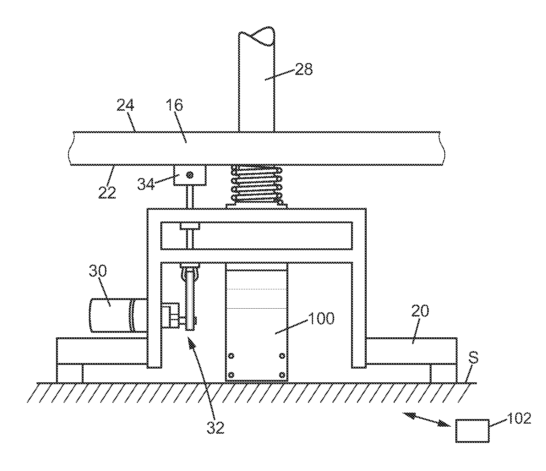
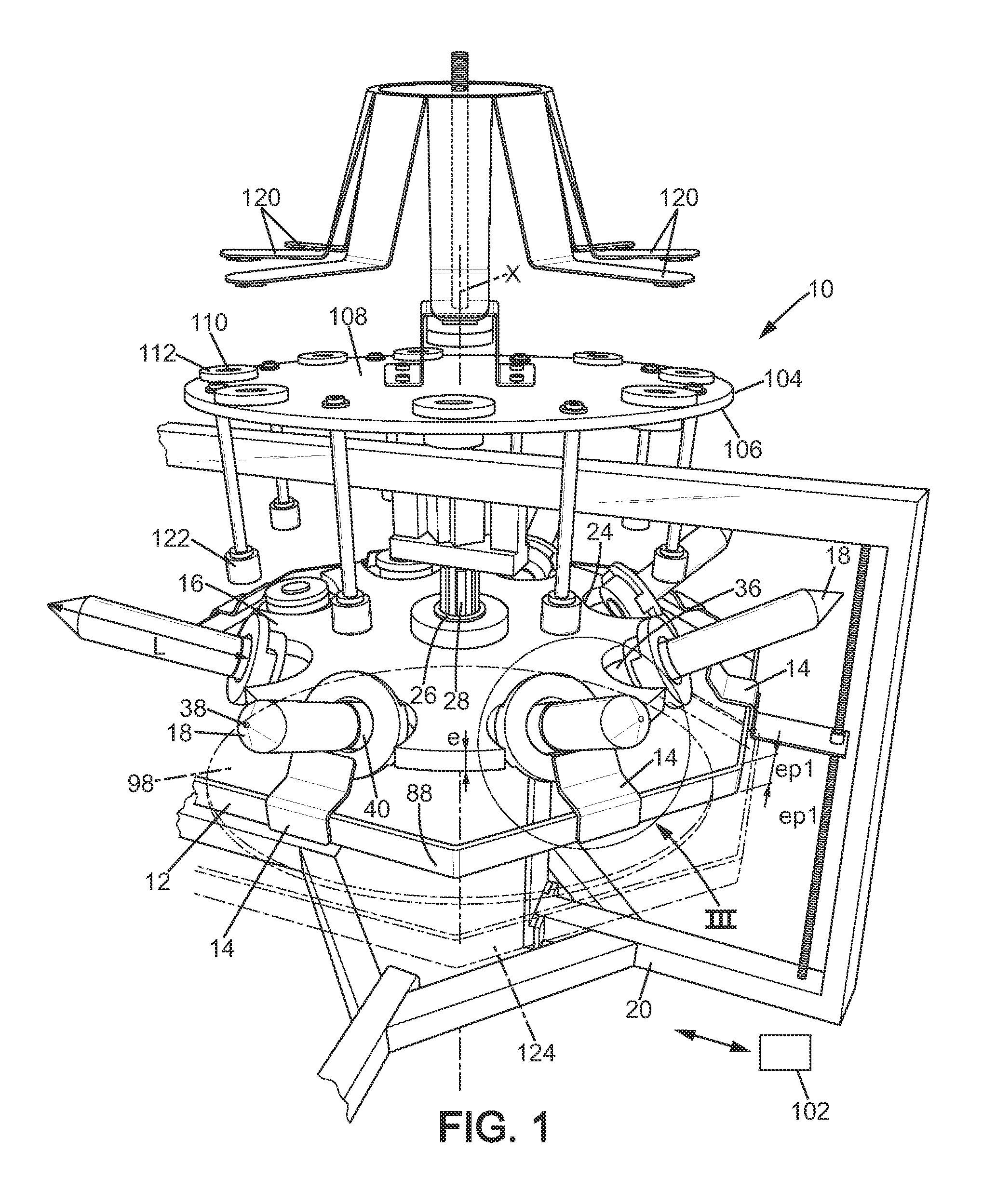
[0063]FIG. 1 illustrates a shaking device 10 according to the invention. The shaking device 10 includes a first plate 12. The first plate 12 comprises a stop 14. The shaking device further comprises a second plate 16. The second plate 16 supports a container 18. The first plate 12 and the second plate 16 form a substantially flat structure. However in implementation variants, the first and / or second plate 12, 16 can be like a wheel, or be another structure than flat or circular.

[0064]The first plate 12 and the second plate 16 are mounted each assembled to a frame 20. Typically, the frame 20 of the shaking device 10 rests on a support S (which can be the ground or a tabletop for example). The support S defines a plane. Subsequently, the description is made with reference to the case where the first plate 12 and the second plate 16 are arranged subs...


PUM

PropertyMeasurementUnit
angleaaaaaaaaaa
angleaaaaaaaaaa
interior volumeaaaaaaaaaa

Abstract

Device for shaking and centrifuging a content including a material in the pulverulent state and a liquid product in a rigid container in preparation for a test on the mixed content, where the container has a capacity less than one liter and suited to a quantity of content specific for the test to be done, including a frame, a plate, a first drive unit and a second drive unit suited for displacing the plate relative to the frame. The first drive unit is suited for displacing the plate relative to the frame with an alternating movement along a shaking direction in order to shake the container, and the second drive unit is suited for displacing the plate relative to the frame according to a rotational movement around a centrifuging axis, such that the content of the container is centrifuged when the plate is rotated around the centrifuging axis.

Description

FIELD OF THE INVENTION[0001]The present invention relates to the technical domain of devices for shaking and centrifuging a content comprising a material in the pulverulent state and a liquid product in a rigid container in order to perform a test on the mixed content, wherein the container has a capacity less than one liter and suited to a quantity of content specific for the test to be done.[0002]The tests on samples comprising shaking and centrifuging steps are widespread. However, shaking the sample is often done manually in a first step before the sample is placed in a device for centrifuging. These handling operations of the container containing the sample are tedious and can lead to handling errors which could falsify the tests and / or require the test be redone.[0003]The “AACC—Method 56-11” standard established by ACC International, for example, imposes precise conditions on shaking and centrifuging samples of flour and solvent mixtures in order to characterize the flour. To ...

Claims


Application Information

Patent Timeline
Patent Type & Authority Applications(United States)
IPC IPC(8): B04B9/10
CPCB04B9/10B01F11/0275B01F11/0025B01F15/0237B01F15/00805B04B5/0421B01F3/12B01F15/0295B01F23/50B01F31/25B01F31/861B01F35/453B01F35/7174B01F35/7548B01F31/50
Inventor MELES, JEAN-PIERRE
Owner CHOPIN TECH
Learn More