Mercury-free lead-free button battery

Active Publication Date: 2014-10-02
LIU BIN
View PDF5 Cites 2 Cited by
  • Summary
  • Abstract
  • Description
  • Claims
  • Application Information

AI Technical Summary

Benefits of technology

[0029]First, the negative cap and the anode material are separated from contacting each other by the partition unit arranged therebetween, so the battery is free from the risk of hydrogen evolution reaction. The present invention uses the partition unit instead of the indium- or tin-plated anode material that is used conventionally to separate the metal matrix of the negative cap. This on one hand ensures the disconnection between the anode material and the negative cap, thereby effectively preventing the battery from expansion, weeping or explosion that would otherwise happen when the anode material and the negative cap contacts each other, eliminating the related safety concern, and improving the safety of the battery, and on the other hand eliminates the process of pl

Problems solved by technology

First, due to its own configuration, the negative cap tends have some electroplating-related problems happening in the indium- or tin-plated layer, such as uneven thickness, less density, porosity, and tendencies towards scratch, removal, oxidization and whiskers.
Poor electroplating on the negative cap increases the risk of contact between the anode material and the negative cap's metal matrix made of low hydrogen overpotential metal such as iron.
Such contact can lead to hydrogen evolution reaction that generates hydrogen and puts the mercury-free lead-free button battery in risk o

Method used


Image

  • Mercury-free lead-free button battery
  • Mercury-free lead-free button battery
  • Mercury-free lead-free button battery

Examples


Embodiment Construction

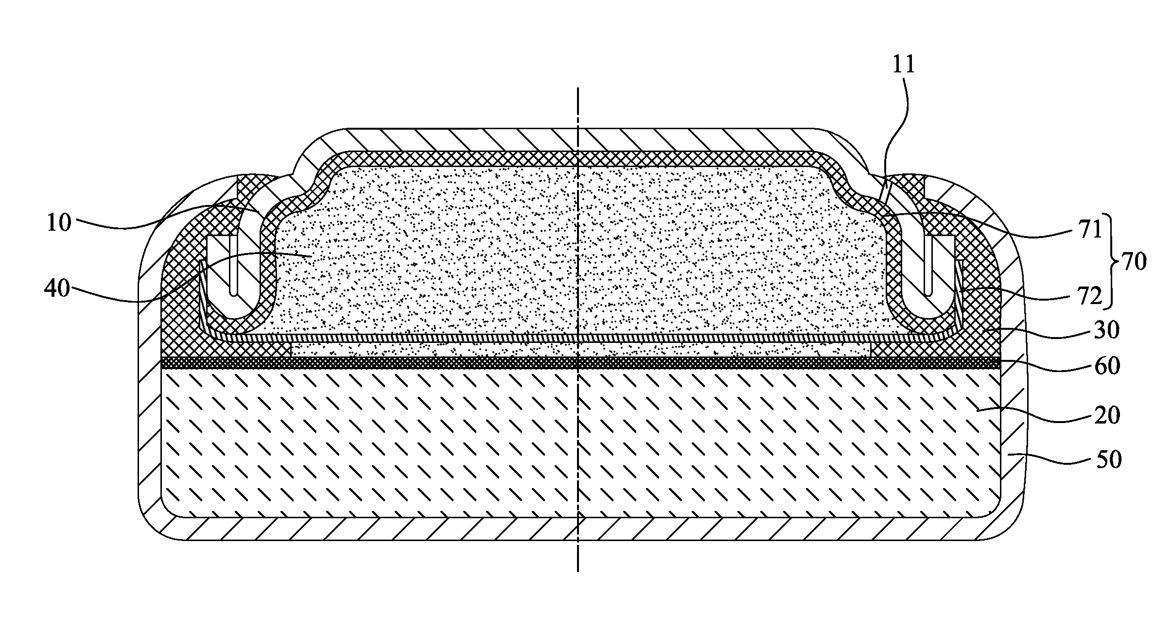
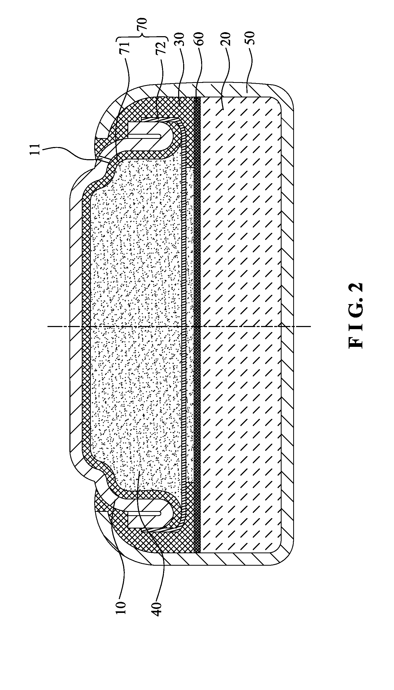
[0040]Please refer to FIG. 2 for the configuration of the first preferred embodiment of the present invention, which comprises a negative cap 10, a cathode material 20, a gasket ring 30, an anode material 40 conductively connected to the negative cap 10, a positive can 50 and a diaphragm 60 for separating the cathode material 20 from the anode material 40.

[0041]The positive can 50 and the negative cap 10 are combined in a buckling manner. The gasket ring 30 is damped between the positive can 50 and the negative cap 10, so as to separate the positive can 50 from the negative cap 10. The cathode material 20 is deposited on the inner bottom of the positive can 50. The diaphragm 60 is arranged on the cathode material 20. The anode material 40 is installed between the negative cap 10 and the diaphragm 60. The anode material 40 is mercury-free lead-free zinc gel.

[0042]Therein, the negative cap 10 is made by punching an iron sheet or an iron-based metal sheet. The negative cap is plated wi...


PUM


Abstract

A mercury-free lead-free button battery includes a negative cap, a cathode material, a gasket ring, a positive can, an anode material, and a diaphragm. The positive can and the negative cap are combined. The gasket ring is clamped between the positive can and the negative cap for separating the positive can from the negative cap. The cathode material is arranged on the bottom of the positive can. The diaphragm is arranged on the cathode material. The anode material is arranged between the negative cap and the diaphragm. A partition unit is arranged between the negative cap and the anode material for separating the anode material from the negative cap and conductively connecting the anode material and the negative cap. The partition unit ensures disconnection between the anode material and the negative cap and therefore safety of the battery by preventing expansion, weeping and even that would otherwise happen.

Description

BACKGROUND OF THE INVENTION[0001]1. Technical Field[0002]The present invention relates to manufacturing of chemical power sources and batteries, and more particularly to mercury-free lead-free button batteries, including alkaline zinc-manganese button batteries and silver oxide button batteries.[0003]2. Description of Related Art[0004]Please refer to FIG. 1 for the typical configuration of a conventional button battery, which comprises a negative cap 10′, a cathode material 20′, a gasket ring 30′, an anode material 40′, a positive can 50′ and a diaphragm 60′ that separates the cathode material 20′ from the anode material 40′. The positive can 50′ and the negative cap 10′ are combined in a buckling manner. The gasket ring 30′ is damped between the positive can 50′ and the negative cap 10′, so as to separate the positive can 50′ from the negative cap 10′. The cathode material 20′ is deposited on an inner bottom of the positive can 50′. The diaphragm 60′ is arranged on the cathode mate...

Claims


Application Information

Patent Timeline
IPC IPC(8): H01M10/04H01M50/167H01M50/474H01M50/486
CPCH01M2/14H01M2/0222H01M2/0287H01M2/12H01M10/0427H01M2/04H01M2/0413Y02E60/10H01M50/109H01M50/171H01M50/124H01M50/30Y02P70/50H01M50/486H01M50/474H01M50/167H01M10/285
Inventor LIU, BIN
Owner LIU BIN
Why Eureka
Try Eureka