Method For Detection Of Loss Of Refrigerant

a technology of refrigerant loss and detection method, which is applied in the direction of refrigeration safety arrangement, temperature measurement of flowing materials, refrigeration machines, etc., can solve the problems of system malfunction, system components damage, and system performance reduction,

Active Publication Date: 2015-01-08
CARRIER CORP
View PDF5 Cites 27 Cited by
  • Summary
  • Abstract
  • Description
  • Claims
  • Application Information

AI Technical Summary

Benefits of technology

[0007]The refrigerant charge within a refrigerant vapor compression system is monitored for early detection of refrigerant charge loss in the refrigerant vapor compression system. In an aspect of the method, a control initiates either a service alarm or a shut down alarm depending on the degree of loss of the refrigerant charge.
[0008]A method is provided for detecting in real-time a refrigerant charge loss in a refrigerant vapor compression system. If both a sensed evaporator outlet superheat exceeds a target evaporator outlet superheat by at least a preset amount of superheat and a sensed degree of openness of an electronic expansion valve exceeds a preset degree of openness for a preset time of period, and a sensed air temperature of either a flow of supply air having traversed the evaporator or a flow of return air returning to the evaporator is changing at a rate less than preset air temperature rate of change, a service alarm is generated indicating a loss of charge warning.
[0009]In a further aspect of the method, a sensed air temperature of either a flow of supply air having traversed the evaporator or a flow of return air returning to the evaporator is changing at a rate less than preset air temperature rate of change, a sensed suction pressure of refrigerant passing to a suction inlet to the compression device is compared to a preset low suction pressure limit. If the sensed suction pressure of refrigerant passing to a suction inlet to the compression device is less than the preset low suction pressure limit for a preset period of time, a shut down alarm is generated warning an urgent system refrigerant recharge is required.

Problems solved by technology

Additionally, transport refrigerant vapor compression systems are subject to cycling between an operating mode and standstill mode, i.e. an idle state.
An inadequate refrigerant charge can reduce system performance and can lead to system malfunction and damage to system components such as the compressor.
It is possible for the refrigerant charge in the system to be initially too low due to human error in filling the system with refrigerant at the manufacturing site or during field installation.
It is also possible for the refrigerant charge to be reduced during operation of the system due to leaks which, if undetected and unaddressed, result in the refrigerant charge dropping low enough that system performance is adversely affected and system components damaged.

Method used


Image

  • Method For Detection Of Loss Of Refrigerant
  • Method For Detection Of Loss Of Refrigerant
  • Method For Detection Of Loss Of Refrigerant

Examples


Embodiment Construction

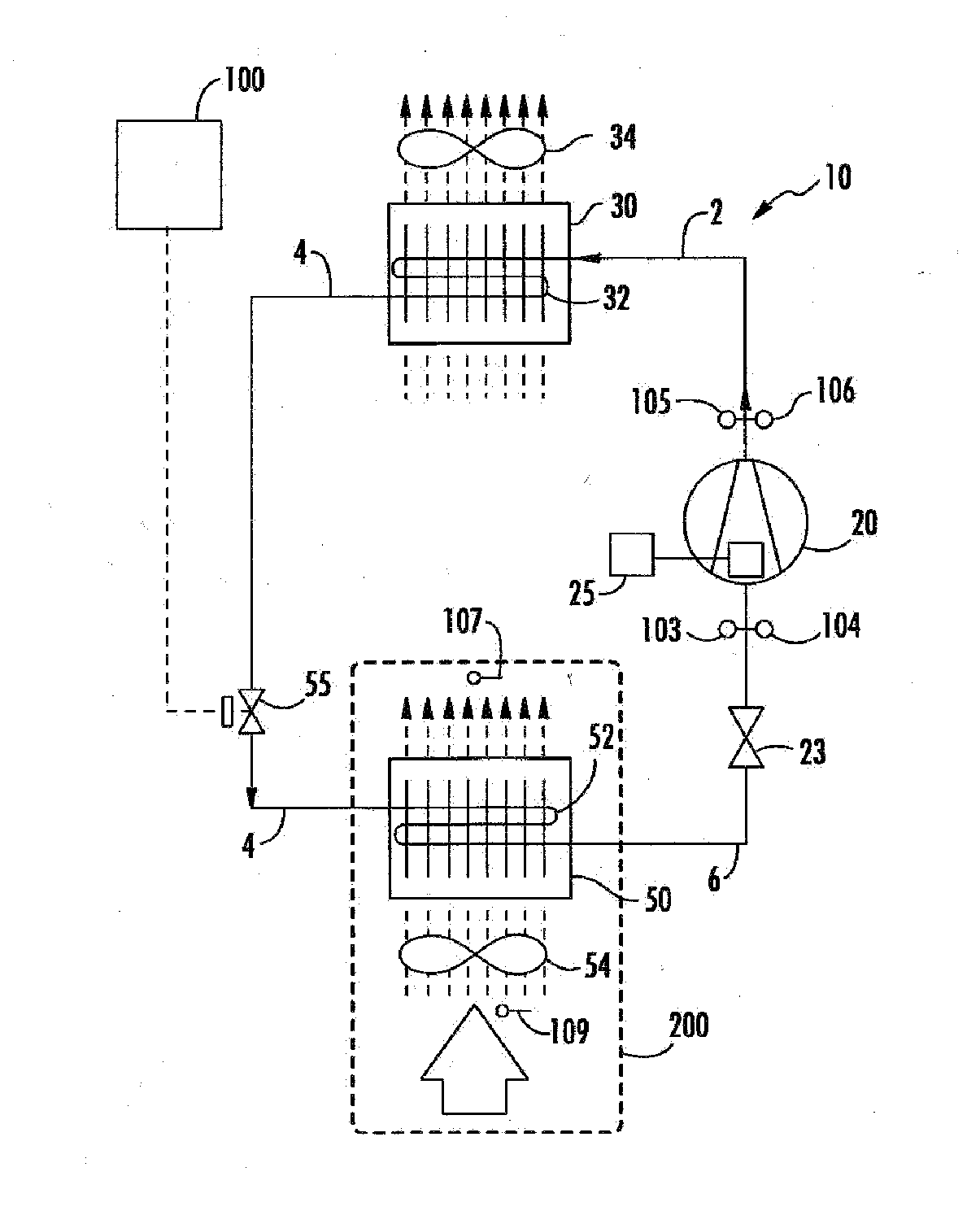
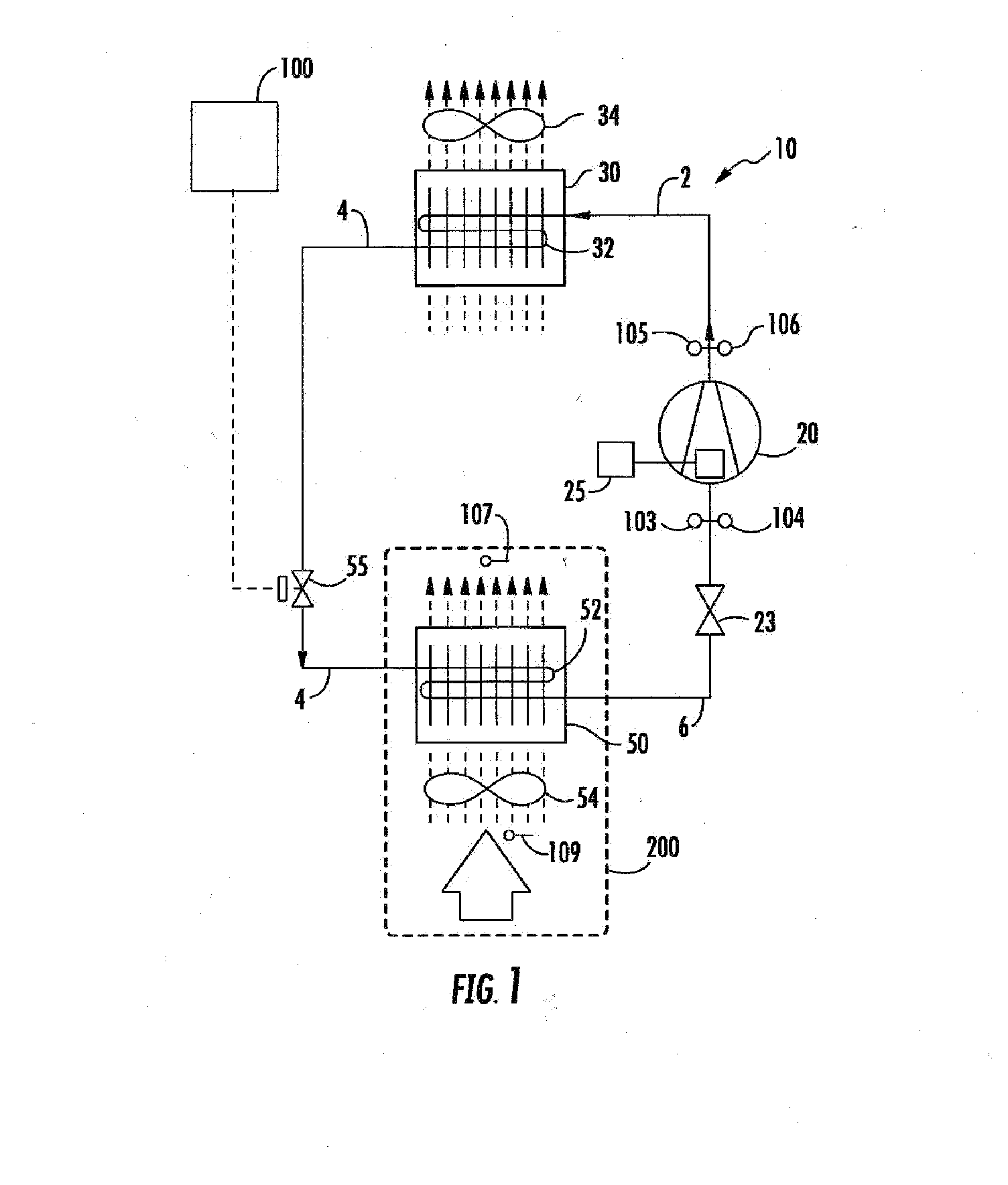
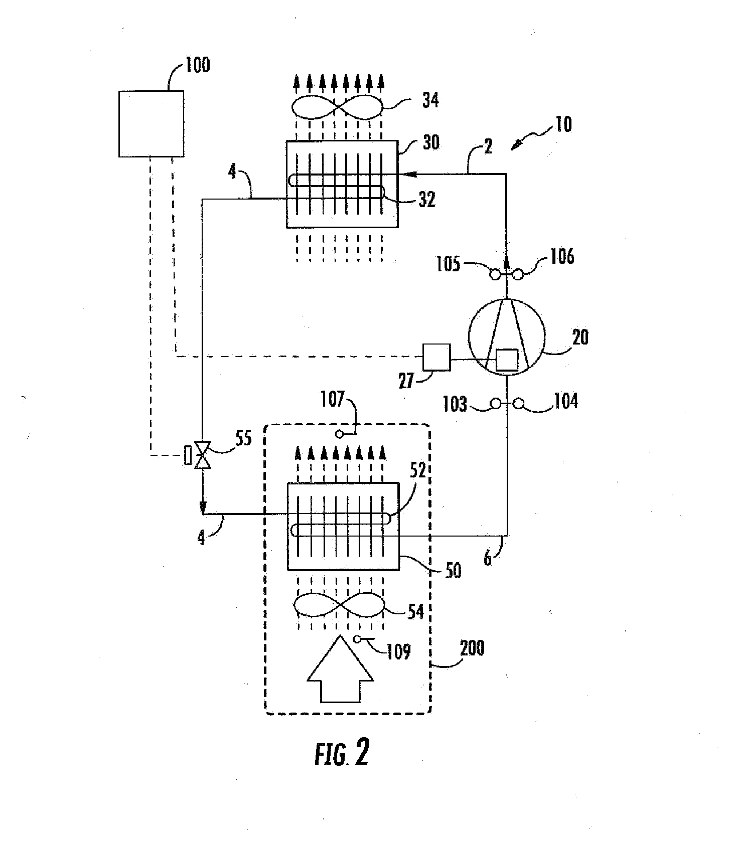
[0016]Referring initially to FIGS. 1-3 of the drawing, there are depicted various exemplary embodiments of a refrigerant vapor compression system, generally designated 10, to which the method for detecting and / or diagnosing a loss of refrigerant charge as disclosed herein is applicable. The refrigerant vapor compression systems 10 are depicted in connection with refrigerating the air or other gaseous atmosphere within the temperature controlled cargo space 200 of a truck, trailer, container or the like for transporting perishable / frozen goods. However, the refrigerant vapor compression systems may also be used in conditioning air to be supplied to a climate controlled comfort zone within a residence, office building, hospital, school, restaurant or other facility, or in refrigerating air supplied to display cases, merchandisers, freezer cabinets, cold rooms or other perishable / frozen product storage areas in commercial establishments.

[0017]Each of the refrigerant vapor compression s...


PUM

PropertyMeasurementUnit
temperature rateaaaaaaaaaa
pressureaaaaaaaaaa
pressureaaaaaaaaaa

Abstract

A method is provided for detecting in real-time a refrigerant charge loss in a refrigerant vapor compression system. If both a sensed evaporator outlet superheat exceeds a target evaporator outlet superheat by at least a preset amount of superheat and a sensed degree of openness of an electronic expansion valve exceeds a preset degree of openness for a preset time of period, and a sensed air temperature of either a flow of supply air having traversed the evaporator or a flow of return air returning to the evaporator is changing at a rate less than preset air temperature rate of change, a service alarm is generated indicating a loss of charge warning.

Description

BACKGROUND OF THE INVENTION[0001]This invention relates generally to vapor compression systems and, more particularly, to detection of a loss of refrigerant in a refrigerant vapor compression system.[0002]Conventional vapor compression systems typically include a compressor, a heat rejection heat exchanger, a heat absorption heat exchanger, and expansion device, commonly an expansion valve, disposed upstream with respect to working fluid flow, of the heat absorption heat exchanger and downstream of the heat rejection heat exchanger. These basic system components are interconnected by working fluid lines in a closed circuit, arranged in accord with known vapor compression cycles.[0003]In some vapor compression systems, capacity modulation capability may be added by incorporating a flash tank economizer into the working fluid circuit between the heat rejection heat exchanger and the evaporator. In such case, the working fluid leaving the heat rejection heat exchanger is expanded throu...

Claims


Application Information

Patent Timeline
Patent Type & Authority Applications(United States)
IPC IPC(8): F25B45/00F25B49/00G01K13/02
CPCF25B45/00F25B2345/003F25B49/00G01K13/02F25B2500/222F25B2600/024F25B2600/2513F25B2700/171F25B2700/1931F25B2700/1933F25B2700/21151F25B2700/21152F25B2700/21172F25B2700/21173F25B49/005F25B2400/13F25B2600/026F25B2700/151
Inventor LIU, LUCY YISUN, JIAN
Owner CARRIER CORP
Why Eureka
Try Eureka