
Integrated dive suit

a dive suit and integrated technology, applied in the field of dive suits, can solve the problems of heavy, bulky, uncomfortable to wear, difficult to handle tanks,

Inactive Publication Date: 2015-01-08
HECR
View PDF14 Cites 8 Cited by
  • Summary
  • Abstract
  • Description
  • Claims
  • Application Information

AI Technical Summary

Benefits of technology

The present invention provides an integrated dive suit with improved features and functionality. The dive suit includes a flexible material shaped to fit a diver's body and is equipped with a pressure vessel, flexible conduit, a manifold, a high pressure regulator, an air fill source, and a buoyancy control device. The pressure vessel is connected to the flexible conduit and the manifold through flexible joints, and the buoyancy control device includes an inflatable bladder and a tube coiled about the weight member. The invention addresses all of the deficiencies of prior art integrated dive suits and provides a more complete solution.

Problems solved by technology

These diving cylinders or tanks are heavy, usually at least 25-30 lbs., bulky and uncomfortable to wear out of the water.
Women, being of smaller stature, find these tanks especially difficult to handle.
Diving cylinders of this type are particularly problematical for certain specialize types of diving such as cave diving or wreck diving in which the diver must often maneuver through tight openings.
This type of bulky cylinder can easily become caught in such small openings and represents a threat to the safety of the diver.
In addition, the concentration of weight in the diving cylinder makes it especially difficult to maneuver when the diver is not in the water.
Conventional containers for this purpose are normally cylindrical in shape and usually made of steel or aluminum and thus are cumbersome to wear and relatively heavy in weight.

Method used


Image

  • Integrated dive suit
  • Integrated dive suit
  • Integrated dive suit

Examples


Embodiment Construction

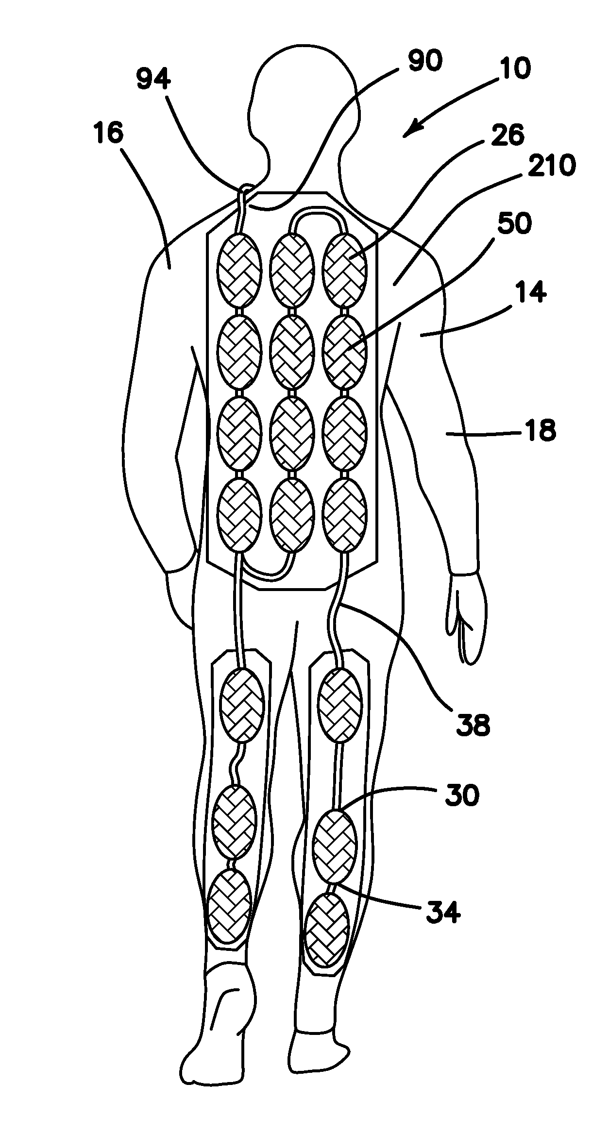
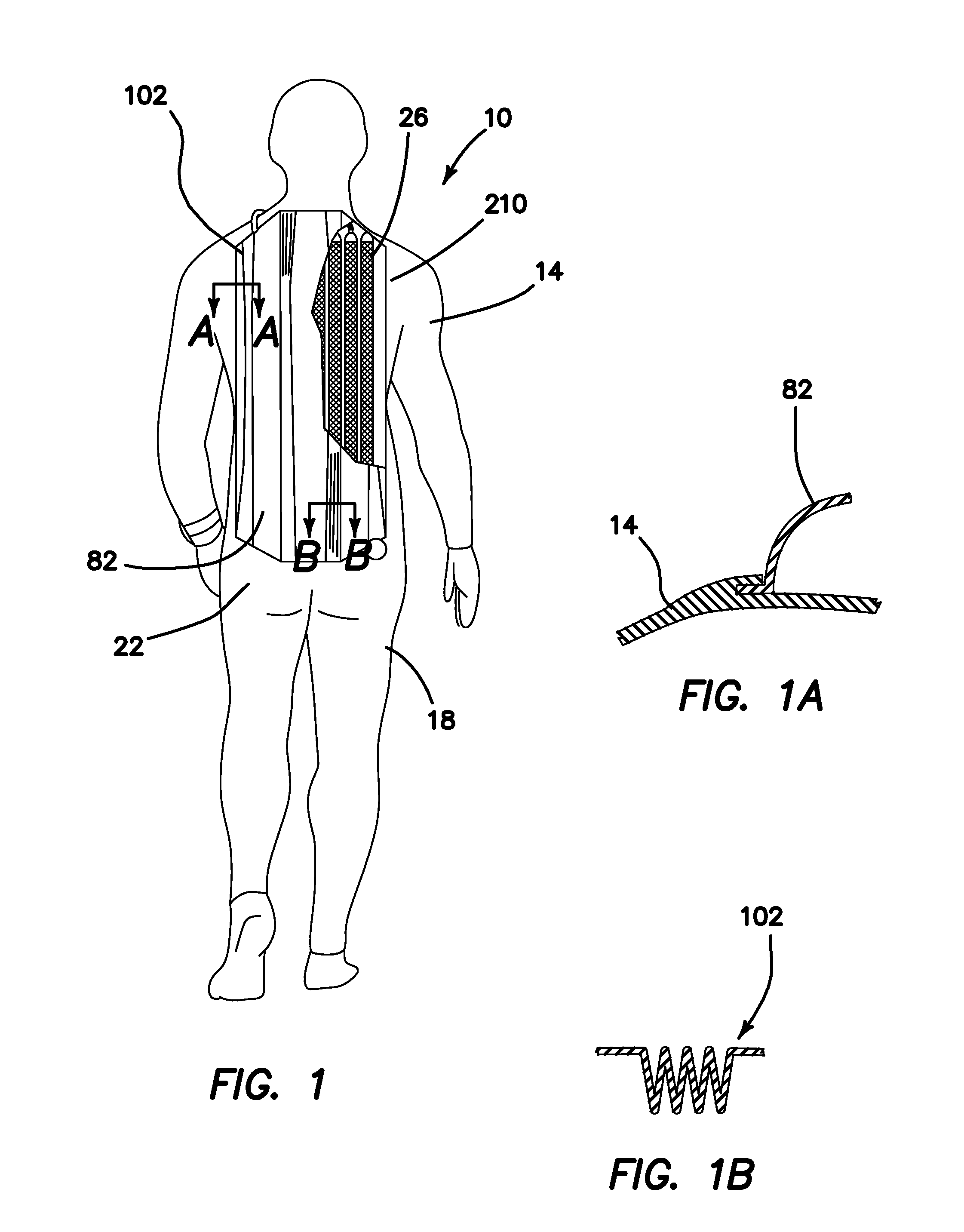
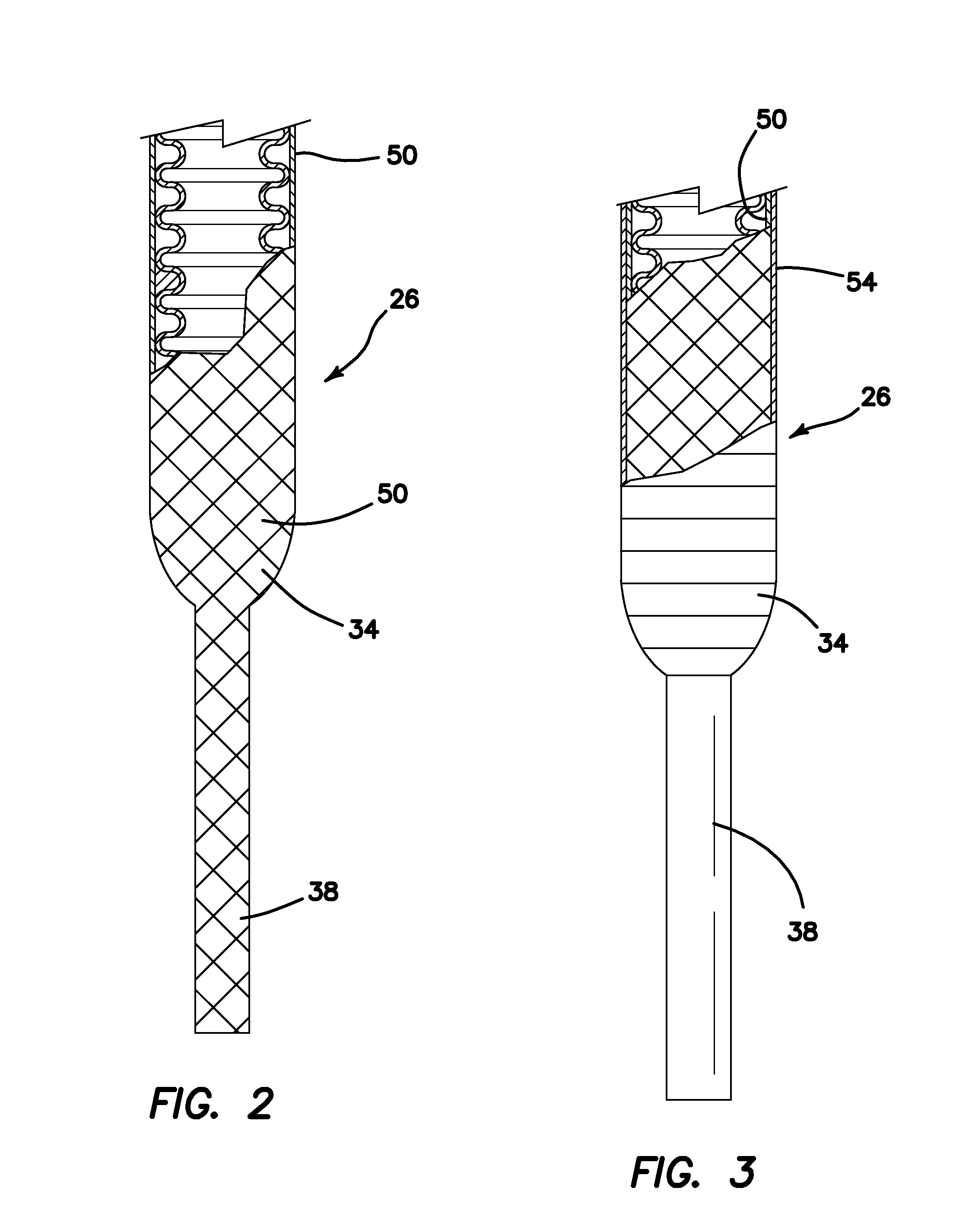
[0094](1) FIGS. 1, 8 and 9 illustrate an integrated dive suit 10 providing the desired features that may be constructed from the following components. A dive suit 14 is provided. The dive suit 14 is formed of flexible material 18 and shaped to fit about a diver's body 22. At least one flexible polymeric pressure vessels 26 is provided. The vessel 26 has a first end 30 and a second end 34. Each of the first 30 and second 34 ends has an attached section of flexible conduit 38. Each of the sections of flexible conduit 38 is attached to either of a sealing fitting 42, an inlet fitting 44, a coupling fitting 48, another section of flexible conduit 38 attached to another vessel 26 or a manifold 46. As illustrated in FIG. 2, the at least one pressure vessel 26 and the sections of flexible conduit 38 are encased in high strength fiber material 50. As illustrated in FIG. 3, the at least one pressure vessel 26 is wrapped with a high strength ballistic ribbon material 54. As illustrated in FIG...


PUM


Abstract

An integrated dive suit includes at least one flexible polymeric pressure vessel connected with sections of flexible conduit to a manifold. The pressure vessel and sections of flexible conduit are encased in high strength fiber material. The pressure vessels are wrapped in high strength ballistic ribbon material. A weight system is integrated with the pressure vessels. The manifold provides connections for a high pressure regulator and an air fill source. A high pressure hose is connected to the high pressure regulator, a low pressure regulator is connected to the low pressure hose and a mouthpiece connected to the low pressure regulator. A hydrodynamic pressure vessel container is integrally attached to the dive suit. A two part, balanced flexible buoyancy control vest, flexible weight pellet containers and a wireless pressure gauge are integrated with the dive suit. A concentrator is used to pressurize a flexible pressure vessel for charging the vessels in the dive suit.

Description

RELATED APPLICATION[0001]The instant application claims priority and incorporates by reference the disclosure thereof in its entirety from U.S. Provisional Application Ser. No. 61 / 733,282 filed Dec. 4, 2012.FIELD OF INVENTION[0002]This invention relates to the field of self-contained underwater breathing systems or SCUBA equipment, and more specifically to dive suits with integrated breathing and buoyancy control systems.BACKGROUND OF THE INVENTION[0003]The first commercially successful scuba equipment was the Aqualung twin hose open circuit design developed by Emile (Gagnan and Jacques-Yves Cousteau in 1942. Present day scuba equipment is similar to this original design except that virtually all modern scuba equipment uses a first stage pressure regulator positioned at the top end of a back mounted diving cylinder with a small second stage regulator held in the teeth of the diver. Both the original Aqualung equipment and modern day scuba gear employ large, relatively heavy metal or...

Claims


Application Information

Patent Timeline
Patent Type & Authority Applications(United States)
IPC IPC(8): B63C11/08B63C11/18B63C11/30B63C11/02
CPCB63C11/08B63C11/02B63C11/186B63C2011/085B63C2011/026B63C2011/303B63C2011/046B63C11/30B63C11/22
Inventor SANDERS, STAN A.
Owner HECR
Learn More