Injector Orifice Plate Filter

a technology of injector orifice plate and filter, which is applied in the direction of machines/engines, manufacturing tools, mechanical equipment, etc., can solve the problems of clogging the described internal parts, affecting the accuracy of the operation of the filter, and affecting the accuracy of the filter

Inactive Publication Date: 2015-01-08
CATERPILLAR INC
View PDF4 Cites 12 Cited by
  • Summary
  • Abstract
  • Description
  • Claims
  • Application Information

AI Technical Summary

Benefits of technology

[0008]One aspect of the disclosure includes a fuel injector configured to be responsive to fuel pressure controlled by an electronic fuel pressure controller having a control orifice plate. The control orifice plate may include at least one internal orifice, and may be formed to have an upper and a lower surface. A circumferential groove may extend about the exterior of the control orifice plate, and a hoop filter defining a wall may be juxtaposed tightly against, and extend about, the circumference of the orifice plate. The hoop filter may fully overlie the circumferential groove, and the internal orifice may intersect the groove.
[0009]In another aspect of the disclosure, a fuel injection pressure control system may have an electronic fuel pressure controller, and may include a fuel injector having at least one control orifice plate configured to be responsive to fuel pressure controlled by the electronic fuel pressure controller. The control orifice plate may include at least one internal orifice, and may be formed having an upper and a lower surface. A circumferential groove may extend about the exterior of the control orifice plate, and a hoop filter having a wall may be juxtaposed tightly against, and extend about, the circumference of the orifice plate. The hoop filter may overlie the circumferential groove, and the internal orifice may intersect the groove.
[0010]In a further aspect of the disclosure, a method of manufacturing a hoop filter configured for filtering a circular orifice plate of a fuel injector may include forming the filter as a high temperature metal ring defining a continuous wall, and laser etching a plurality of radially extending apertures through the wall. The apertures may be formed such that any given aperture dimension is no larger than 50 microns. The hoop filter may be tightly banded about the circumference of the orifice plate, which may include a circumferential groove.

Problems solved by technology

Such debris can otherwise clog the described internal parts of the injector, and deleteriously interfere with their accurate functioning.
In extremely large engines, however, such approach may not be practical due to excessive pressure drops.

Method used


Image

  • Injector Orifice Plate Filter
  • Injector Orifice Plate Filter
  • Injector Orifice Plate Filter

Examples


Embodiment Construction

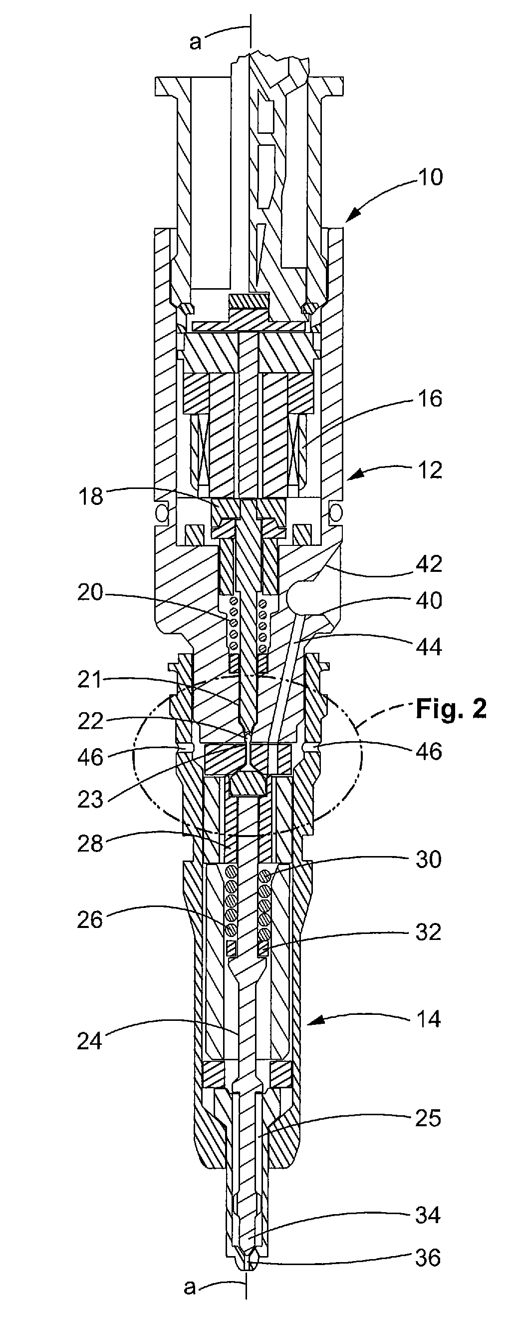
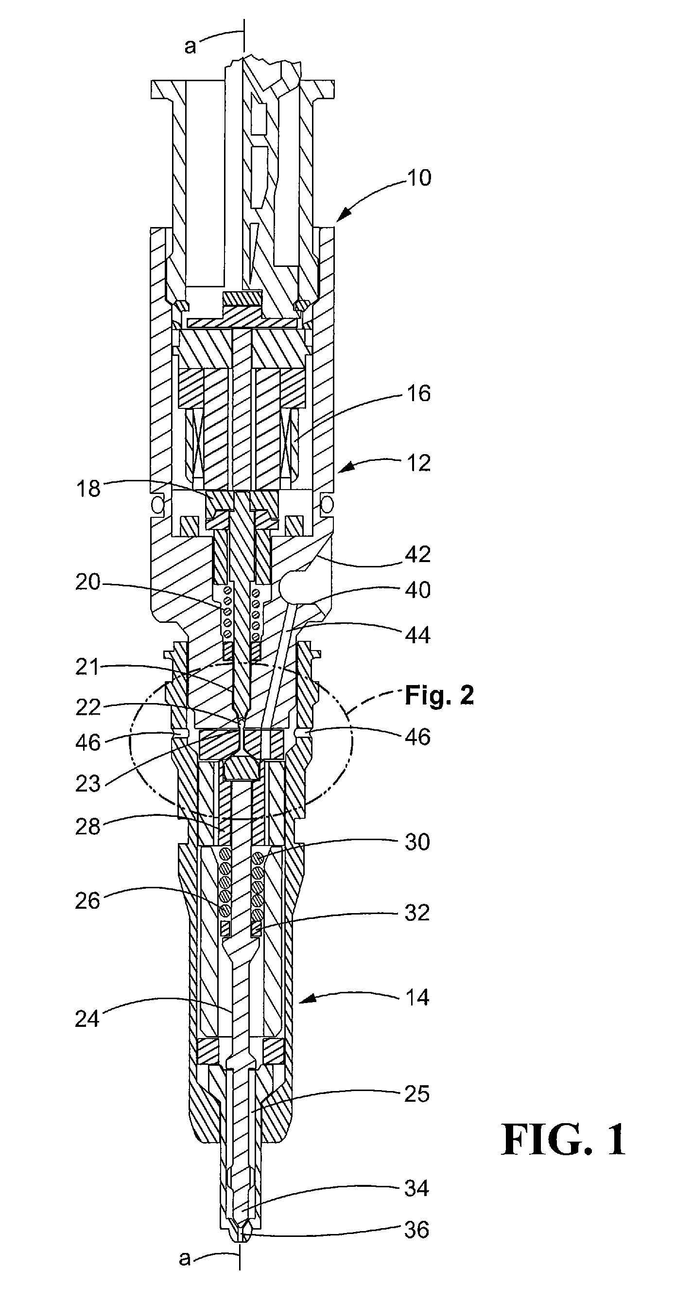
[0015]Referring initially to FIG. 1, a common rail fuel injector 10 includes an upper body portion 12 and a lower body portion 14, each portion 12, 14 containing various components to be described. The fuel injector 10 includes an axis “a-a” about which the upper and lower body portions 12, 14 are oriented. Although the upper and lower body portions 12, 14 are shown as separate structures, albeit secured together, they could alternatively be formed as a single unitary structure.

[0016]In the upper body portion 12 of the fuel injector 10, an electronic actuator 16 may be actuated by either a solenoid or piezo electronic actuating system, as may be appreciated by those skilled in this art. The actuator 16 may be directly coupled to an armature 18. As such, the actuator 16 may be adapted for mechanically moving a fuel pressure control valve 22 against the force of a control valve biasing spring 20. In the fuel injector 10, the spring 20 normally biases a control valve pusher 21 against ...


PUM

PropertyMeasurementUnit
pressureaaaaaaaaaa
sizeaaaaaaaaaa
pressureaaaaaaaaaa

Abstract

A hoop filter is adapted to protect a pressure control orifice plate in a common rail fuel injector from being plugged by contaminated fuel. Shaped in the form of a band, the filter is configured to engage the circumference of a pressure control orifice plate. For purposes of filtration, the orifice plate has a circumferential groove which intersects at least one internal orifice; the groove is externally covered by the body of the hoop filter. In one embodiment, the band-shaped hoop filter has small apertures adapted to filter out any particle having a size greater than 50 microns. In another disclosed embodiment, the hoop filter is a solid band-shaped edge filter without any apertures; instead the orifice plate periphery includes circumferentially spaced vertical grooves which interface with the bottom and top edges of the filter to restrict entry of contaminant particles.

Description

TECHNICAL FIELD [0001]This disclosure relates generally to systems and methods for protecting common rail electronic fuel injection systems from potential damage by contaminated fuels. More particularly, the disclosure relates to fuel filters adapted to keep particulate matter from plugging orifices of fuel pressure control orifice plates used in fuel injectors of such systems.BACKGROUND[0002]Common rail fuel injector systems are typically associated with internal combustion engines, and most often with diesel engines, for supplying fuel to power such engines. The injectors include needle valves moveable within nozzle pressure control chambers. Each needle valve is adapted to open and close a nozzle outlet for injecting fuel into a combustion cylinder in response to controlled pressure level changes within the nozzle pressure control chamber.[0003]Typically, each fuel injector includes an injector body having a fuel inlet, at least one nozzle outlet, and a drain outlet. Each injecto...

Claims


Application Information

Patent Timeline
Patent Type & Authority Applications(United States)
IPC IPC(8): F02M61/16
CPCF02M61/168F02M61/165F02M47/027F02M2200/02F02M2200/28F02M2200/8061F02M2200/8069Y10T29/49826
Inventor MACK, DAVID CLARENCE
Owner CATERPILLAR INC
Why Eureka
Try Eureka