Display device

a display device and organic el technology, applied in the field of organic el display devices, can solve problems such as reducing contrast, and achieve the effect of suppressing contrast deterioration and reducing reflection of ligh

Active Publication Date: 2015-01-08
SHARP KK
View PDF19 Cites 7 Cited by
  • Summary
  • Abstract
  • Description
  • Claims
  • Application Information

AI Technical Summary

Benefits of technology

[0037]The display device of the present invention is configured so that each of the plurality of picture elements has a first region and a second region which is provided on a periphery of the first region, the first region is a display region, and the second region has a multilayer film which includes a plurality of layers having respective different refractive indexes, the multilayer film reducing reflection of light thanks to optical interference.
[0038]It is therefore possible to realize a display device which can suppress a deterioration in contrast.

Problems solved by technology

However, since the organic EL display device has a high external-light reflectance, it has a problem of reducing its contrast when used near a window or outdoors.

Method used


Image

  • Display device
  • Display device
  • Display device

Examples


embodiment 1

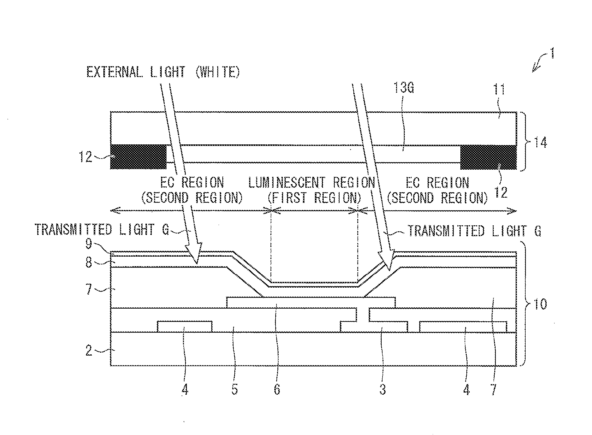
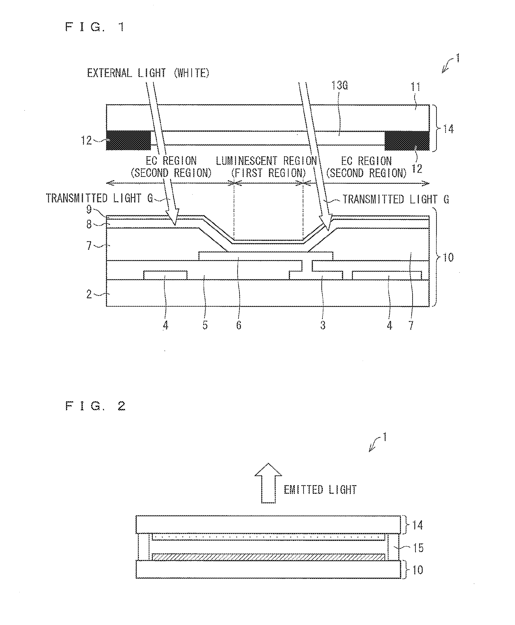
[0054]FIG. 2 is a cross-sectional view schematically illustrating a configuration of an organic EL display device 1.

[0055]As illustrated in FIG. 2, the organic EL display device 1 includes (i) a support substrate 10, (ii) a sealing substrate 14 which is provided so as to face the support substrate 10, and (iii) a sealant resin 15 which bonds the support substrate 10 and the sealing substrate 14 to each other.

[0056]The organic EL display device 1 of Embodiment 1 has a hollow region which is enclosed by the sealant resin 15, the support substrate 10, and the sealing substrate 14. The hollow region may have, for example, a filler resin layer region.

[0057]The organic EL display device 1 is a top-emission type organic EL display device which emits, via the sealing substrate 14, light generated on the support substrate 10.

[0058]Note that, according to Embodiment 1, a luminescent layer which emits white (W) light is employed, and a microcavity structure (later described) is introduced. The...

embodiment 2

[0112]The following description will discuss Embodiment 2 of the present invention with reference to FIGS. 6 and 7. Embodiment 2 is identical to Embodiment 1 except that, in Embodiment 2, an EC region (second region) has, between an organic layer 8 and a second electrode 9, an optical path adjustment layer 18 which (i) is made from a material having a refractive index substantially equal to that of the organic layer 8 and (ii) partially transmits light whose wavelength falls within a predetermined range. For convenience, identical reference numerals are given to members having respective functions identical to those illustrated in the drawings of Embodiment 1, and their descriptions are omitted in Embodiment 2.

[0113]FIG. 6 is a cross-sectional view schematically illustrating a configuration of an organic EL display device la. As illustrated in FIG. 6, each EC region (second region) of a support substrate 10a of the organic EL display device la has, between an organic layer 8 and a s...

embodiment 3

[0116]The following description will discuss Embodiment 3 of the present invention with reference to FIG. 8. Embodiment 3 is different from Embodiments 1 and 2 in that, in Embodiment 3, an optical interference layer is provided in an EC region (second region) of an organic EL display device 20 which is produced by use of a selective application method. Other configuration of Embodiment 3 is identical to that of Embodiment 1. For convenience, identical reference numerals are given to members having respective functions identical to those illustrated in the drawings of Embodiments 1 and 2, and their descriptions are omitted in Embodiment 3.

[0117]FIG. 8 is a view schematically illustrating a configuration of the organic EL display device 20 which is produced by use of the selective application method.

[0118]On a substrate 21 provided are TFTs 22, an interlayer insulating film 23, first electrodes 24, and edge covers 25 (see FIG. 8).

[0119]A hole injection and transport layer 26 is provid...


PUM


Abstract

An EC region (second region) of an organic EL display device (1) has an optical interference layer which is a multilayer of (i) an edge cover (7) made from an acrylic resin having a lower refractive index, (ii) an organic layer (8), and (iii) a second electrode (9) which is a thin and semi-transparent film. Therefore, the organic EL display device (1) can suppress a deterioration in contrast without narrowing a display region, and can have a high reliability.

Description

TECHNICAL FIELD[0001]The present invention relates to an organic EL display device.BACKGROUND ART[0002]Recently, various flat panel displays have been developed. Particularly, an organic EL (ElectroLuminescence) display device has gained a great deal of attention as an excellent flat panel display because it can realize low power consumption, reduction in thickness, and high definition.[0003]However, since the organic EL display device has a high external-light reflectance, it has a problem of reducing its contrast when used near a window or outdoors.[0004]How the organic EL display device carries out full-color display is classified into, for example, two large methods. That is, the organic EL display device carries out full-color display by use of (i) an EL layer which emits red light, green light, and blue light (selective application method) or (ii) an EL layer which emits white light, a color filter which transmits red light, a color filter which transmits green light, and a co...

Claims


Application Information

Patent Timeline
Patent Type & Authority Applications(United States)
IPC IPC(8): H01L27/32H01L51/52
CPCH01L27/3246H01L51/5265H01L51/5246H01L27/322H01L51/5284H01L51/5275H10K59/38H10K59/122H10K50/852H10K50/86H10K50/865H10K2102/3026H10K50/858H10K50/8426
Inventor OCHI, TAKASHINIBOSHI, MANABUKAWATO, SHINICHITSUKAMOTO, YUTOKIKUCHI, KATSUHIROKOSAKA, TOMOHIRO
Owner SHARP KK
Why Eureka
Try Eureka