
Antenna control system and multi-frequency shared antenna

a control system and antenna technology, applied in the field of mobile communication antennas, can solve the problems of severe interference to high frequency radiation units, coaxial nesting, and certain limits, and achieve the effects of improving the convergence of reducing interference, and improving the horizontal plane half power beam width

Active Publication Date: 2015-01-08
COMBA TELECOM TECH (GUANGZHOU) CO LTD
View PDF3 Cites 11 Cited by
  • Summary
  • Abstract
  • Description
  • Claims
  • Application Information

AI Technical Summary

Benefits of technology

The invention is about a multi-frequency shared antenna that can maintain its size and good electric performance. This means that the antenna can work with multiple frequencies without being too big or losing quality.

Problems solved by technology

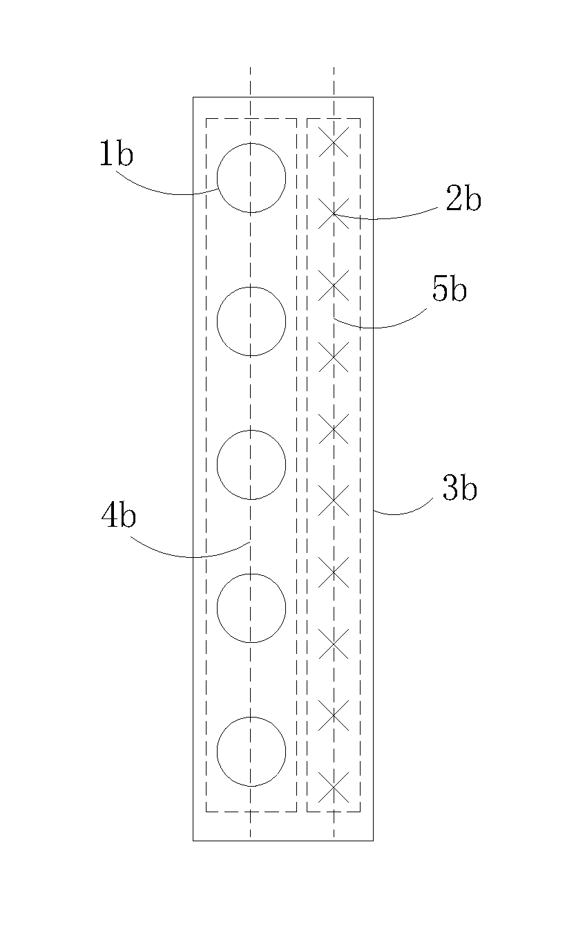
It has been found in practice that coaxial nesting technique shown in FIG. 1 suffers from certain limit during use and there are at least two drawbacks.
No matter what sort of array pitch is selected from above ranges for high and low frequency, when all the high frequency radiation units 2b and low frequency radiation units 1b are coaxial, radiation arms of some low frequency radiation units 1b will locate over the high frequency radiation units 2b, thereby causing severe interference to high frequency radiation units 2b, and greatly increasing difficulty in design of high frequency radiation array radiation characteristics.
However, this will also increase half-power beam width in horizontal plane of the low frequency radiation units 1b and therefore no desired results may be obtained.
Further, transmission loss as well as antenna gain loss is increased due to lengthening of main feeder line of upper high frequency radiation array.
This solution suffers from shortcoming such as substantial increase of antenna width.
Due to dramatic asymmetry between left and right radiation boundary of the low and high frequency radiation arrays together with cross-interference between the two arrays, problem such as direction deflection of horizontal plane beam of the two arrays and cross polarization ratio deterioration arises.
This results in increased difficulty in design.

Method used


Image

  • Antenna control system and multi-frequency shared antenna
  • Antenna control system and multi-frequency shared antenna
  • Antenna control system and multi-frequency shared antenna

Examples


Embodiment Construction

[0053]The present invention is described in further detail in conjunction with various embodiments and accompanied drawings.

[0054]It is well known that a radiation array (including low frequency and high frequency radiation array) is intended to transmit communication signals and is generally constituted by a plurality of radiation units arranged in matrix in the form of a single or multiple lines. As to high frequency signals, a high frequency radiation array is formed by plural high frequency radiation units. Correspondingly, a low frequency radiation array is formed by plural low frequency radiation units. Here, in a radiation unit, a component for transmitting and receiving signals is a symmetrical dipole of the unit. An electrical component of the symmetrical dipole is its radiation arm which is supported by a balun of the symmetrical dipole. In a radiation unit, to improve gain of polarization diversity receiving, two pairs of symmetrical dipoles are employed and they are arra...


PUM


Abstract

A multi-frequency shared antenna comprises a low frequency radiation array and a first high frequency radiation array both of which are disposed on a reflection plate and provided with power by different feeding networks. The first high frequency radiation array comprises a number of high frequency radiation units, at least partial high frequency radiation units are arranged on a same axis which overlaps one of two axes of the low frequency radiation array, in all high frequency radiation units arranged on said axis, at least partial high frequency radiation units are nested with the low frequency radiation units arranged on the same axis, and the orthogonal projection area of these nested high frequency radiation units on the reflection plate falls within the orthogonal projection area of the corresponding low frequency radiation units on the same reflection plate.

Description

FIELD OF THE INVENTION[0001]The present invention relates to field of mobile communication antenna and more particularly, relates to a multi-frequency shared antenna and antenna control system based on said multi-frequency shared antenna.BACKGROUND OF THE INVENTION[0002]With increase of mobile communication network standards, to save sites and location, reduce difficulty of estate management coordination, and decrease investment cost, multi-frequency shared antenna sharing a common site and location is eventually becoming a first choice for operators in networking business.[0003]Currently in this industry, two constructions are mainly employed to multi-frequency shared antennae array. One solution is coaxial nesting as denoted in FIG. 1. According to this solution, a low frequency radiation unit 1a and a high frequency radiation unit 2a are coaxially arranged on a same axis 4a of a reflection plate 3a. Another solution is side by side adjoining solution as shown in FIG. 2. In this s...

Claims


Application Information

Patent Timeline
IPC IPC(8): H01Q21/26H01Q21/00H01Q19/10H01Q5/00
CPCH01Q21/26H01Q19/108H01Q21/0006H01Q5/0027H01Q21/24H01Q21/06H01Q5/307H01Q5/42
Inventor SUN, SHAN QIUJIA, FEIFEILIU, PEITAO
Owner COMBA TELECOM TECH (GUANGZHOU) CO LTD
Learn More