
Chromatic Range Sensor Probe Detachment Sensor

a chromatic range and sensor technology, applied in the field of precision measurement instruments, can solve the problems of not being able to easily adapt to a renishaw-type probe head system, entanglement of the sensor, and inability to achieve the desired effect,

Active Publication Date: 2015-01-08
MITUTOYO CORP
View PDF2 Cites 22 Cited by
  • Summary
  • Abstract
  • Description
  • Claims
  • Application Information

AI Technical Summary

Benefits of technology

The patent describes a system where a machine can detect when an optics element on a probe is detached, which could indicate a potential collision with a workpiece. This allows the machine to quickly stop moving and minimize any damage. The system uses existing sensors and wiring, so it can be easily integrated into existing probe heads without needing any additional sensors or wiring. This results in a more efficient and effective system for detecting and preventing collisions during inspection operations.

Problems solved by technology

While Renishaw™ type probe head systems are the most commonly used in the industry, certain technologies are not easily incorporated into Renishaw-type systems.
Furthermore, attempts to upgrade an existing Renishaw-type probe head system to one with more advanced capabilities can entail significant costs and / or inconvenience.
For example, certain technologies adapted to a Renishaw-type probe head system may lack desirable features, lack a desirable level of controllability, and / or lack the capacity for being automatically interchangeable with other types of probes that may be interfaced to the Renishaw-type probe head system.
One particular issue with regard to using Renishaw-type probe head systems, or similar systems, is that the existing data and control connections between the machines and the probes consist of a limited number of wired connections.
This effectively forms a “bottleneck” which makes it difficult to add additional technologies and / or features to a probe that is to be mounted and / or exchanged using the probe head system.
In particular, existing chromatic range sensors have not typically been automatically attachable and / or interchangeable using a Renishaw-type probe head system or the like.
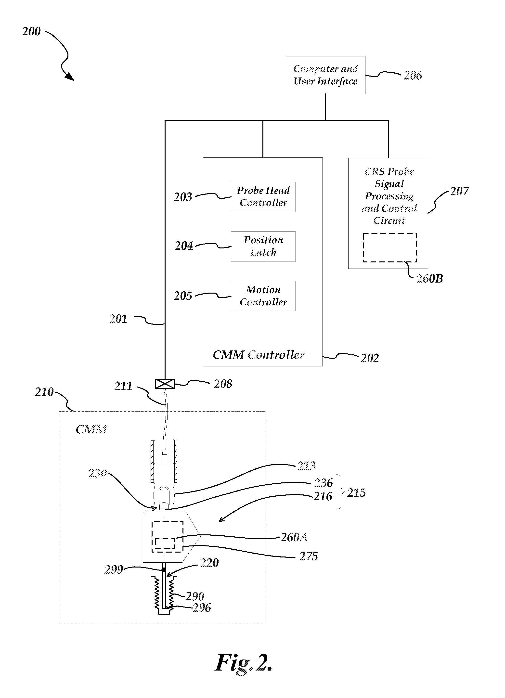
One issue for measuring probes is the danger of a collision with a workpiece.
During such movements, a collision may accidentally occur between the measuring probe and the workpiece or other physical object.
Such collisions may cause damage to the probe, the coordinate measuring machine, and / or the workpiece.

Method used


Image

  • Chromatic Range Sensor Probe Detachment Sensor
  • Chromatic Range Sensor Probe Detachment Sensor
  • Chromatic Range Sensor Probe Detachment Sensor

Examples


Embodiment Construction

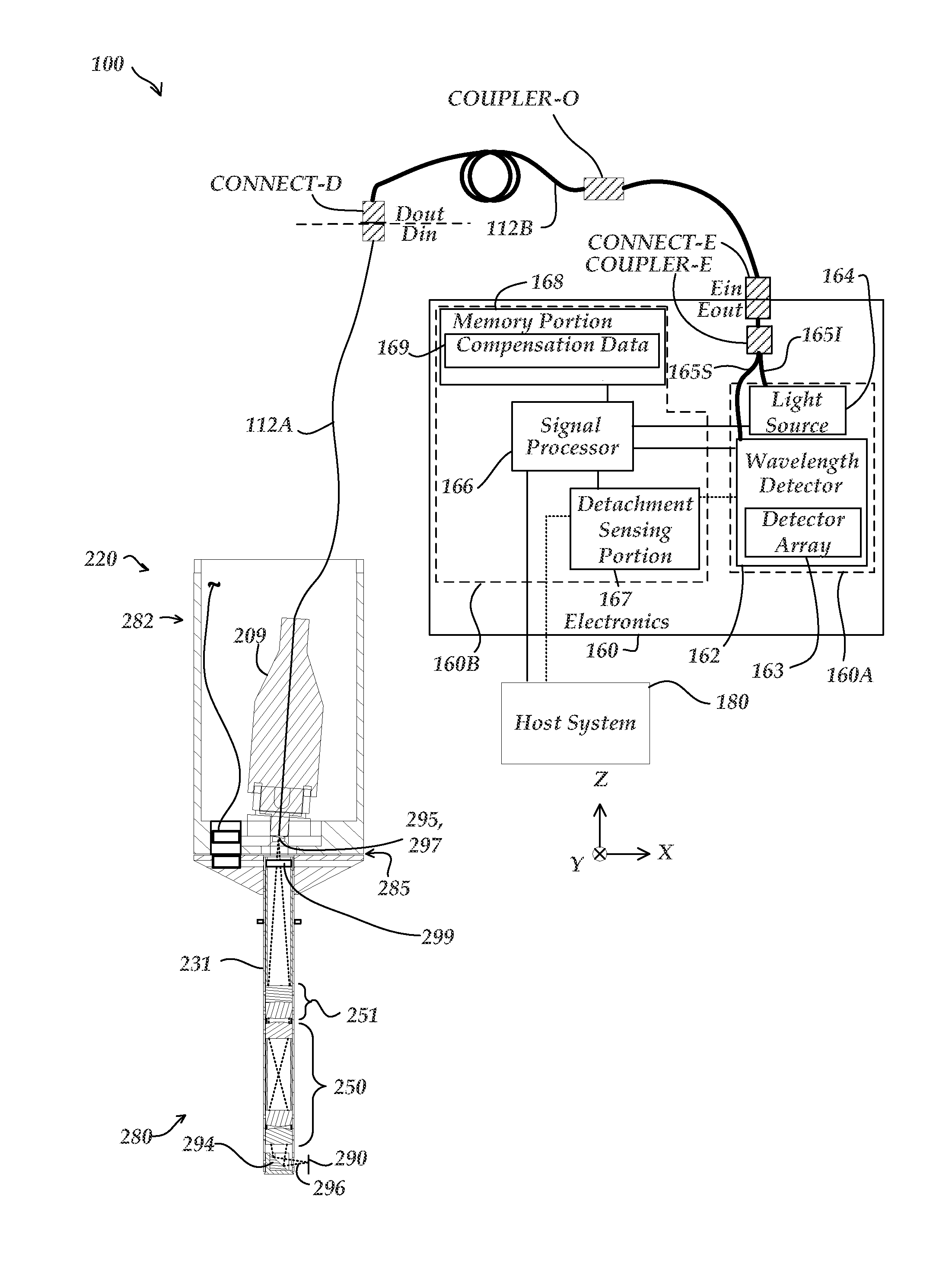
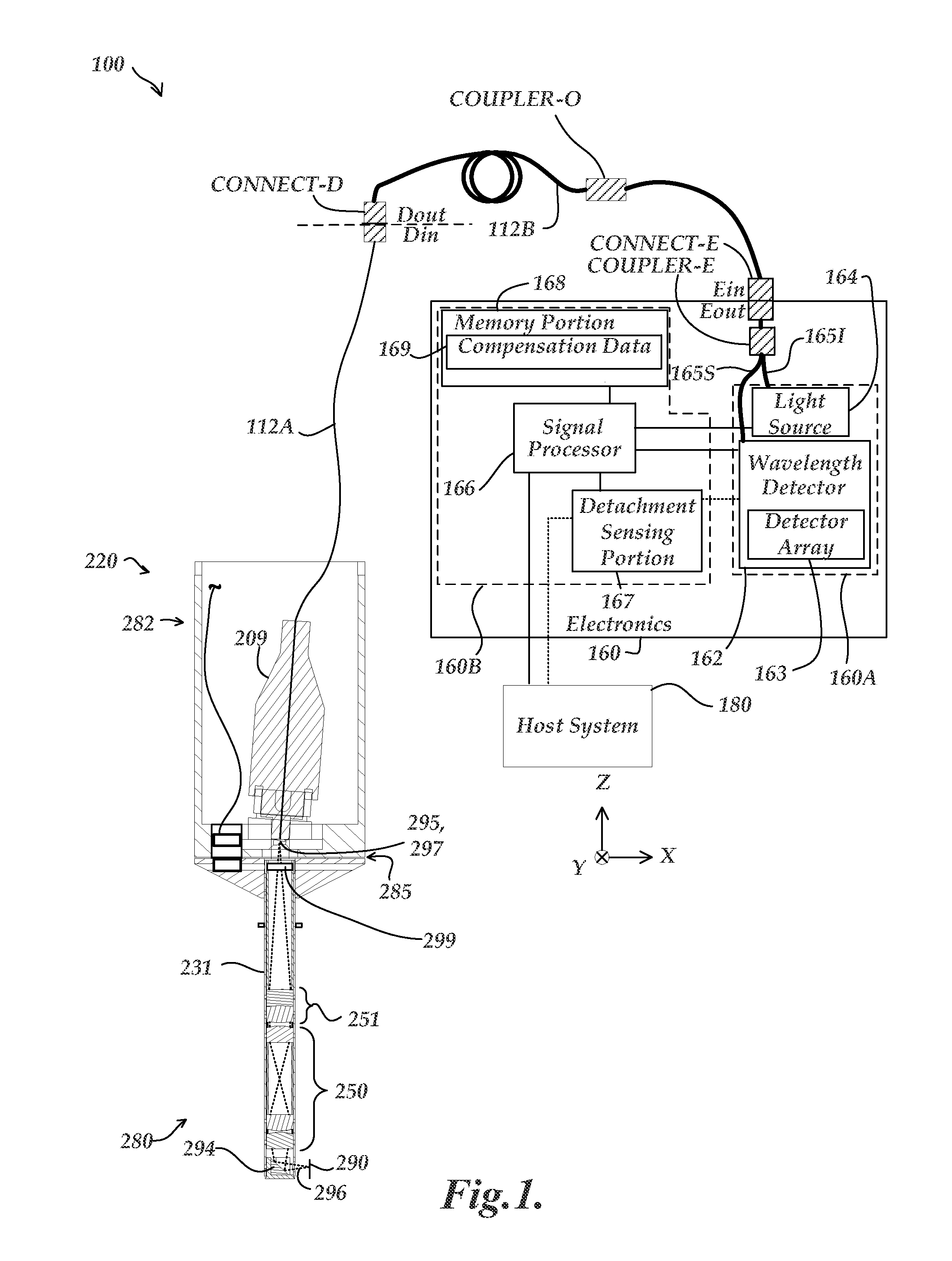
[0028]FIG. 1 is a block diagram of an exemplary chromatic range sensor (CRS) system 100 of a first type based on operating principles that are desirable to employ in conjunction with a coordinate measuring machine (CMM). The CRS system 100 has certain similarities to sensors described in U.S. Pat. Nos. 7,876,456 and 7,990,522 (the '456 and '522 patents, respectively), which are hereby incorporated herein by reference in their entireties. As shown in FIG. 1, the CRS system 100 includes an electronics portion 160 and an optical pen 220. It will be appreciated that the CRS system 100 shown in FIG. 1 is a chromatic point sensor system which measures a single measurement point at a time.

[0029]The optical pen 220 shown in FIG. 1 is an optical pen. However, in various embodiments alternative types of chromatic range systems, such as a chromatic line sensor, may be configured to operate according to the systems and methods disclosed herein. The optical pen 220 is described in more detail in...


PUM


Abstract

A system and method for a chromatic probe detachment sensor is provided. A detachment signal element is included in an interchangeable optics element of a probe. The detachment signal element is configured to substantially transmit a first set of wavelengths corresponding to a measuring range, and at least partially reflect a set of detachment element wavelengths. In one implementation, the detachment signal element comprises a thin film coating such as a sharp edge filter. The detection of a detachment condition can thus be achieved using the existing probe electronics without requiring the addition of other external sensors or wiring to the probe or coordinate measuring machine that utilizes the probe. The sensing of a detachment condition may be utilized to halt further movement of the probe to minimize damage in the event of a collision.

Description

FIELD[0001]The present application relates generally to precision measurement instruments, and more particularly to detachment sensing methods such as may be used in conjunction with a chromatic range sensor probe system for a coordinate measuring machine.BACKGROUND[0002]In various types of coordinate measuring machines, the points on the surface of a workpiece may be sensed with a probe. In one type of probe, the workpiece is directly measured by touching a mechanical contact of the probe to various points along the workpiece surface. In some cases, the mechanical contact is a ball. Certain coordinate measuring machines use both optical and mechanical measuring sensors. Such devices are described in U.S. Pat. Nos. 4,908,951 and 5,825,666, which are hereby incorporated by reference in their entirety. Auto changing racks are also disclosed for holding multiple probes, a probe holder, and lenses for selective mounting on a camera, and the like.[0003]Related to auto changing racks, fre...

Claims


Application Information

Patent Timeline
Patent Type & Authority Applications(United States)
IPC IPC(8): G01B11/14
CPCG01B11/14G01B11/007G01B2210/50
Inventor SESKO, DAVID WILLIAM
Owner MITUTOYO CORP
Learn More