Radio communication system, base station, user terminal, and communication control method
a radio communication system and user terminal technology, applied in the field of radio communication systems, base stations, user terminals, and communication control methods, can solve the problems of uniform reception qualities over all radio resources, and achieve the effect of reducing the overhead of reporting (feedback) from the user terminal connected to the second base station by the adjustment of bias values
- Summary
- Abstract
- Description
- Claims
- Application Information
AI Technical Summary
Benefits of technology
Problems solved by technology
Method used
Image
Examples
first embodiment
[0042](1) Overview of Radio Communication System
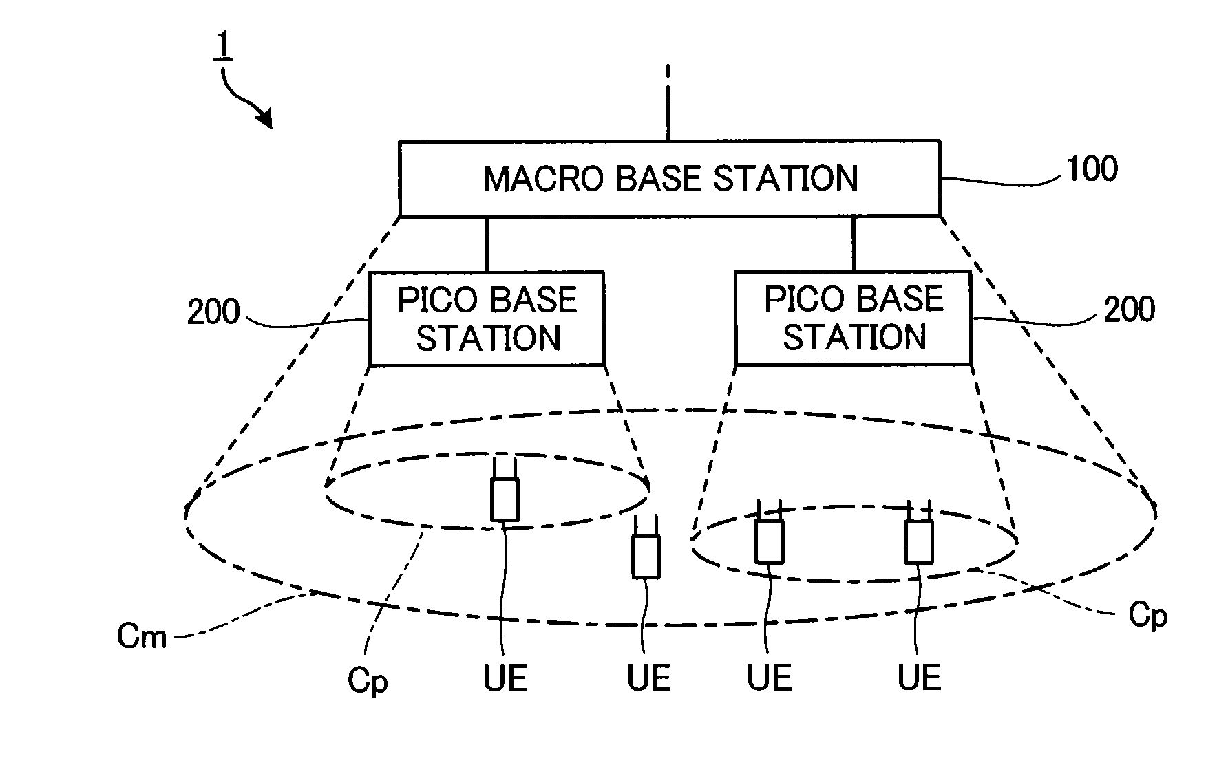
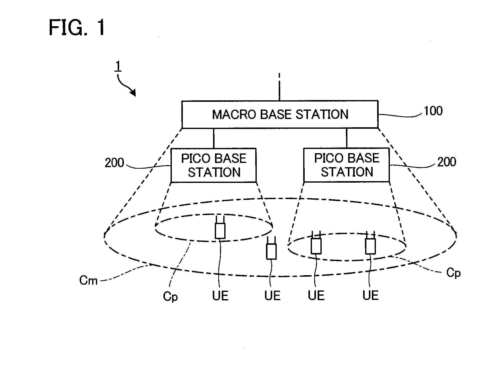
[0043]FIG. 1 is a block diagram illustrating a radio communication system 1 according to an embodiment of the present invention. The radio communication system 1 includes a macro base station (macro eNodeB (evolved Node B)) 100, a pico base station (pico eNodeB) 200, and a user terminal (user equipment) UE. Although only one macro base station 100 is shown in the figure for simplicity, it is naturally to be understood that the radio communication system 1 can include multiple macro base stations 100.
[0044]Radio communication between each communication component (the macro base station 100, the pico base station 200, the user terminal UE, etc.) in the radio communication system 1 is performed according to a predetermined Radio Access Technology, such as LTE (Long Term Evolution). Although the present embodiment describes an example in which the radio communication system 1 operates according to LTE, it is not intended to limit the techn...
second embodiment
[0130]A second embodiment of the present invention is described below. In each embodiment described below, for elements for which operation and function are equivalent to those of the first embodiment, the reference symbols used in the above description are used, and description thereof will be omitted as appropriate.
[0131]As described in “(6) Cell Range Expansion”, by adding the bias value ‘a’ to the received power from the pico base station 200, the area of the picocell Cp formed by the pico base station 200 is pseudo-expanded.
[0132]FIG. 16 illustrates a state of the picocell before expansion (before-expansion picocell RP-Cp) and after Cell Range Expansion (after-expansion picocell CRE-Cp). Hereinafter, a user terminal UE located inside the before-expansion picocell RP-Cp is referred to as a “user terminal RP-UE”, and a user terminal UE connected to the pico base station 200 by the Cell Range Expansion is referred to as a “user terminal CRE-UE”.
[0133]The allocated resource group d...
third embodiment
[0139]In the embodiments described above, the macro base station 100 (the radio communication unit 110) transmits radio signals to the user terminal UE in the non-protected subframes NSF and stops transmitting radio signals in the protected subframes PSF. On the other hand, a macro base station 100 (radio communication unit 110) of the present embodiment transmits radio signals in the protected subframes PSF as well.
[0140]FIG. 17 is a diagram illustrating a state of transmission power of radio signals transmitted by base stations (macro base station 100, pico base station 200) according to the present embodiment. The radio communication unit 210 of the pico base station 200, in a manner similar to that in the aforementioned embodiments, transmits radio signals to a user terminal UE in both the protected subframes PSF and the non-protected subframes NSF. The radio communication unit 110 of the macro base station 100, in the non-protected subframes NSF, transmits radio signals to the ...
PUM
 Abstract
Description
Claims
Application Information
 - R&D
- Intellectual Property
- Life Sciences
- Materials
- Tech Scout
- Unparalleled Data Quality
- Higher Quality Content
- 60% Fewer Hallucinations
Browse by: Latest US Patents, China's latest patents, Technical Efficacy Thesaurus, Application Domain, Technology Topic, Popular Technical Reports.
© 2025 PatSnap. All rights reserved.Legal|Privacy policy|Modern Slavery Act Transparency Statement|Sitemap|About US| Contact US: help@patsnap.com


