System and method for manufacturing a wind turbine blade

Active Publication Date: 2015-01-08
LM WP PATENT HLDG
View PDF18 Cites 4 Cited by
  • Summary
  • Abstract
  • Description
  • Claims
  • Application Information

AI Technical Summary

Benefits of technology

The patent text describes a method for manufacturing wind turbine blades using a relatively expensive blade mold. The method allows for more efficient use of the mold by performing the closing operation away from the blade molds, resulting in a greater throughput of wind turbine blades. The manufacturing system is designed to produce wind turbine blades quickly and efficiently, allowing for maximum use of the blade molds. A post-molding station can be located either within or remote from the blade molds.

Problems solved by technology

High-quality blade moulds are one of the most expensive pieces of equipment in the blade manufacturing process, requiring extensive tooling and manufacture before use to ensure accurate reproduction of desired blade profiles, as well as to allow for the turning of the moulds to bond blade shell parts together.
Blade moulds in use in current processes can cost approximately 1-3 million to manufacture and, dependent on where the moulds are made, extensive transportation time may be a factor before a new mould can be used at a manufacturing plant.
This introduces considerable expense and lead time in the implementation of a manufacturing process for a new wind turbine blade.
Accordingly, one of the limitations to efficient implementation of wind turbine technology is the time required for the initial setup of a blade manufacturing system.
A further limitation is the time taken for the manufacturing of individual blades within such a system.

Method used


Image

  • System and method for manufacturing a wind turbine blade
  • System and method for manufacturing a wind turbine blade
  • System and method for manufacturing a wind turbine blade

Examples


Embodiment Construction

[0159]An embodiment of the invention will now be described, by way of example only, with reference to the accompanying drawings, in which:

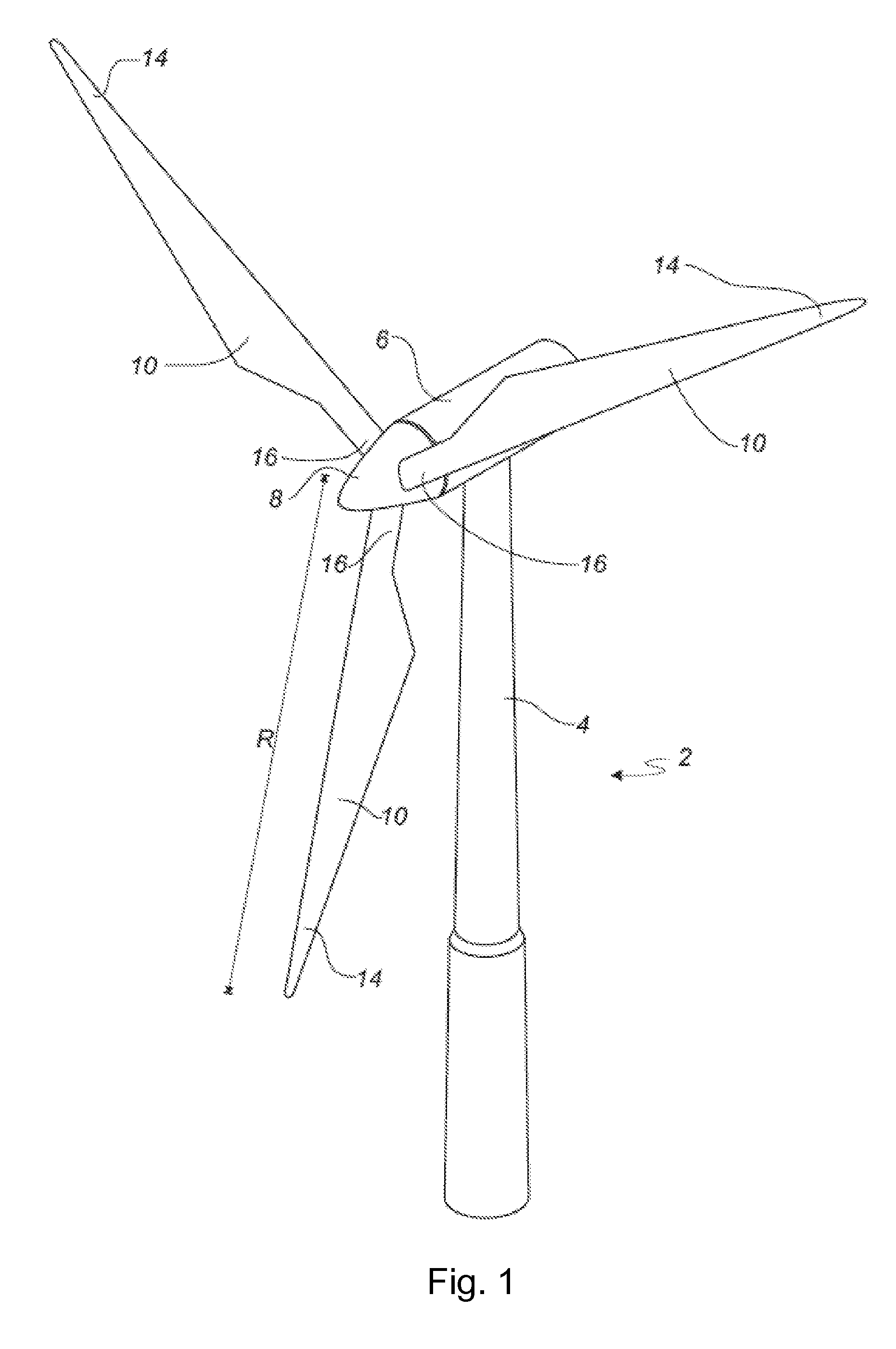
[0160]FIG. 1 shows a wind turbine;

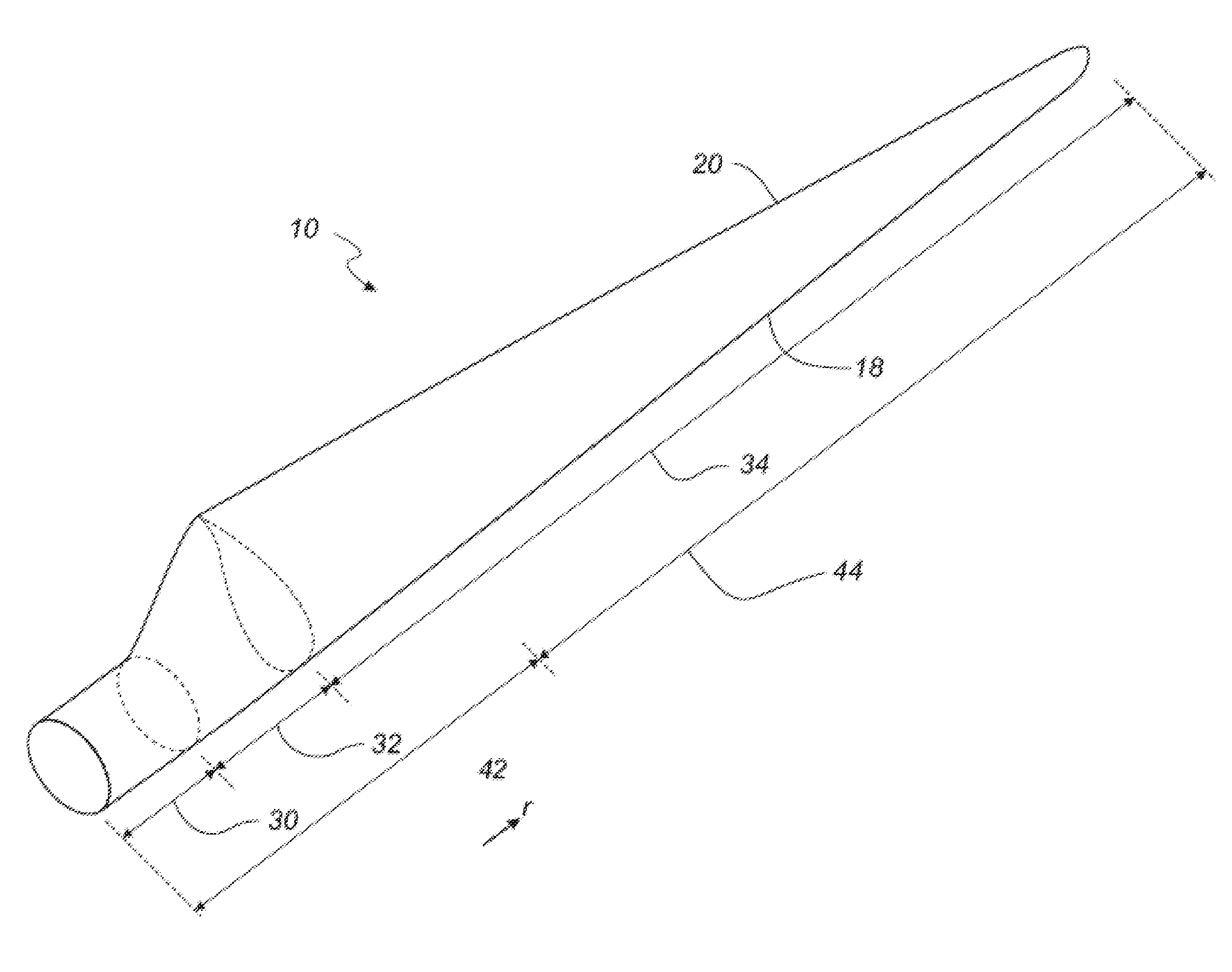
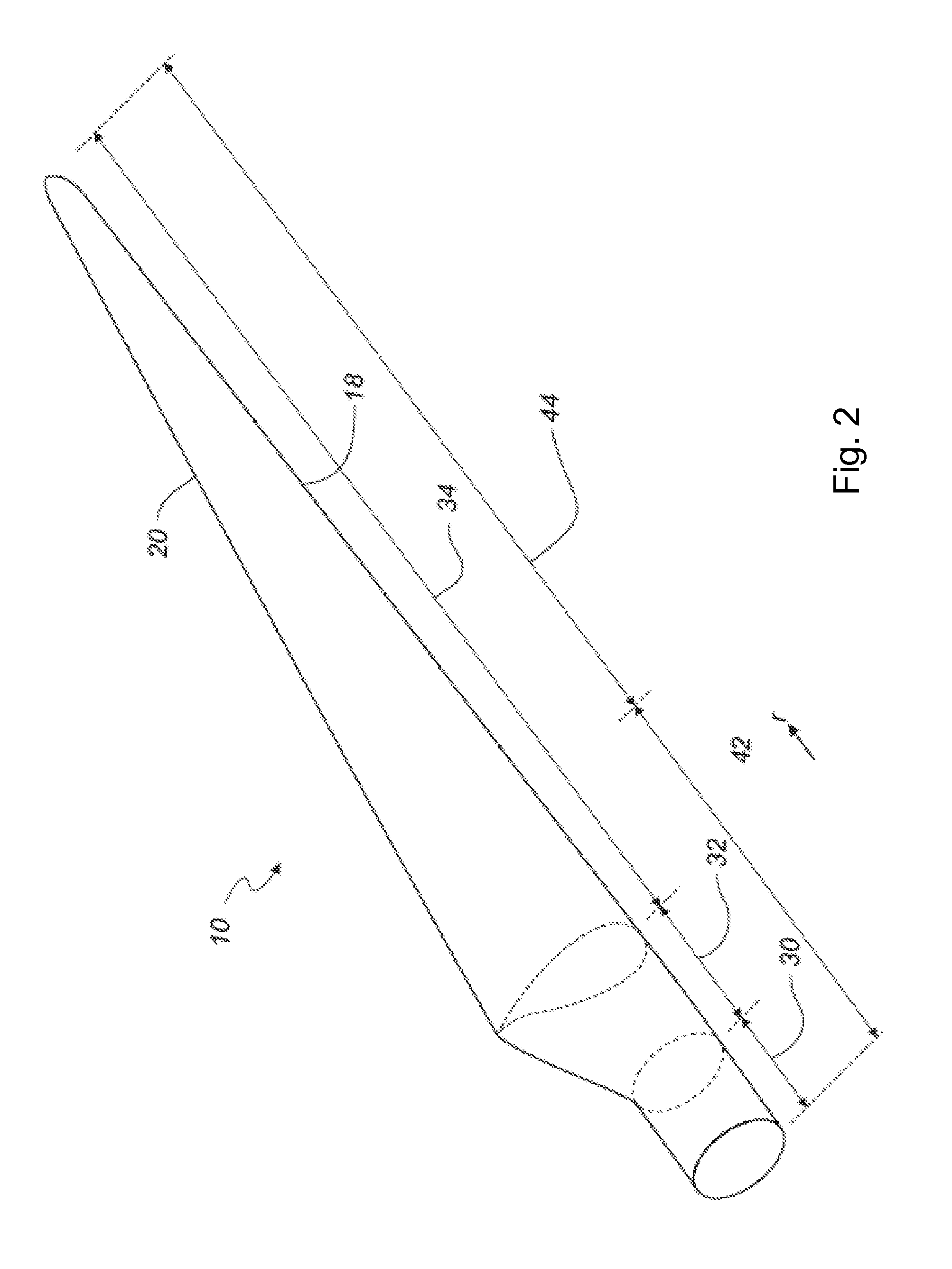
[0161]FIG. 2 shows a schematic view of a wind turbine blade;

[0162]FIG. 3 shows a schematic view of an airfoil profile of the blade of FIG. 2;

[0163]FIG. 4 illustrates an embodiment of a manufacturing process for a wind turbine blade according to the invention;

[0164]FIG. 5 is a top plan view of an embodiment of a post-moulding station for use in the manufacture of a wind turbine blade according to the invention;

[0165]FIG. 6 is a perspective view of the post-moulding station of FIG. 5;

[0166]FIG. 7(a) is a side view of the post-moulding station of FIG. 5 when in an open state;

[0167]FIG. 7(b) is a side view of the post-moulding station of FIG. 5 when in a closed state;

[0168]FIG. 8(a) is an end view of the post-moulding station of FIG. 5 when in an open state;

[0169]FIG. 8(b) is an end view of the post-moulding station o...


PUM

PropertyMeasurementUnit
Lengthaaaaaaaaaa
Forceaaaaaaaaaa

Abstract

A manufacturing method for a wind turbine blade is described which utilises a post-moulding station in the manufacturing process. A blade shell forming part of a wind turbine blade is initially moulded in a blade mould, the blade shell subsequently transferred to a post-moulding station which allows for various post-moulding operations to be carried out on the blade shell away from the mould, thereby increasing the productivity of the blade mould in the manufacturing process. The post-moulding station may be operable to perform the closing of first and second blade shells to form a wind turbine blade, and may be formed from an adjustable structure which can provide relatively easy access to the contained blade shell for working thereon. Accordingly, the manufacturing equipment may be of reduced cost, combined with an increase in the overall productivity of the manufacturing system.

Description

FIELD OF THE INVENTION[0001]The present invention relates to a system and method of manufacture of a wind turbine blade using a post-moulding station.BACKGROUND OF THE INVENTION[0002]Wind turbine blades are normally manufactured as first and second blade shells, using a pair of adjacent blade moulds. The blade moulds comprise first and second moulding surfaces conforming to the upwind and downwind halves (or the suction and pressure sides) of a wind turbine blade, the first blade mould used to form a first blade shell and the second blade mould used to form a second blade shell, the shells subsequently joined together to form a wind turbine blade.[0003]A fibrous composite material is initially layered on top of the first and second moulding surfaces, the layers of material conforming to the contours of the moulds to form the external aerodynamic surfaces of the blade shells. Once sufficient layers of the fibrous material have been applied in the moulds, a resin is applied to the fib...

Claims


Application Information

Patent Timeline
IPC IPC(8): B23P15/04F03D1/06
CPCF03D1/0675B23P15/04B29C65/48B29L2031/085F05B2260/4031B29C65/7802B29C65/7841B29C66/1142B29C66/54B29C31/00F03D15/00Y10T29/49337Y10T29/5137Y02E10/72Y02P70/50
Inventor DE WAAL MALEFIJT, BERNARD WILLEM
Owner LM WP PATENT HLDG
Why Eureka
Try Eureka