
Flashing toothbrush

a toothbrush and flashing technology, applied in the direction of lighting elements, brushes, lighting and heating apparatus, etc., can solve the problems of inability to replace the power supply, inability to fix the circuit board and the batteries inability to use the element to fix the circuit board and the battery in the brush handle, etc., to achieve strong market competitiveness and facilitate operation

Inactive Publication Date: 2015-01-15
SHUMMI ENTERPRISE
View PDF6 Cites 26 Cited by
  • Summary
  • Abstract
  • Description
  • Claims
  • Application Information

AI Technical Summary

Benefits of technology

The present invention provides a lighting toothbrush structure that is easy to operate with one hand, improves hygiene, and has an entertainment function to attract children. Additionally, it has a sucker to save on tooth brush holder expenses. The design features a simple structure, easy repair, and battery replacement, which makes it more convenient and practical.

Problems solved by technology

However, when the power is exhausted, the power supply cannot be replaced.
As a result, the lighting toothbrushes are not practical.
Although it is convenient for a user to replace the batteries of the lighting toothbrush, no element can be used to fix the circuit board and the batteries in the brush handle.
Hence, when a user brushes his teeth, the circuit board and the batteries wobble and collide with the inside wall of the brush handle, whereby the circuit board is easily broken or contact fault of the batteries occur.
Besides, incorrect locking will break the threads, whereby the circuit board and the batteries are not effectively fixed but even drop off.
The installation of the switch causes great distress to hand-disabled people.

Method used


Image

  • Flashing toothbrush
  • Flashing toothbrush
  • Flashing toothbrush

Examples


Embodiment Construction

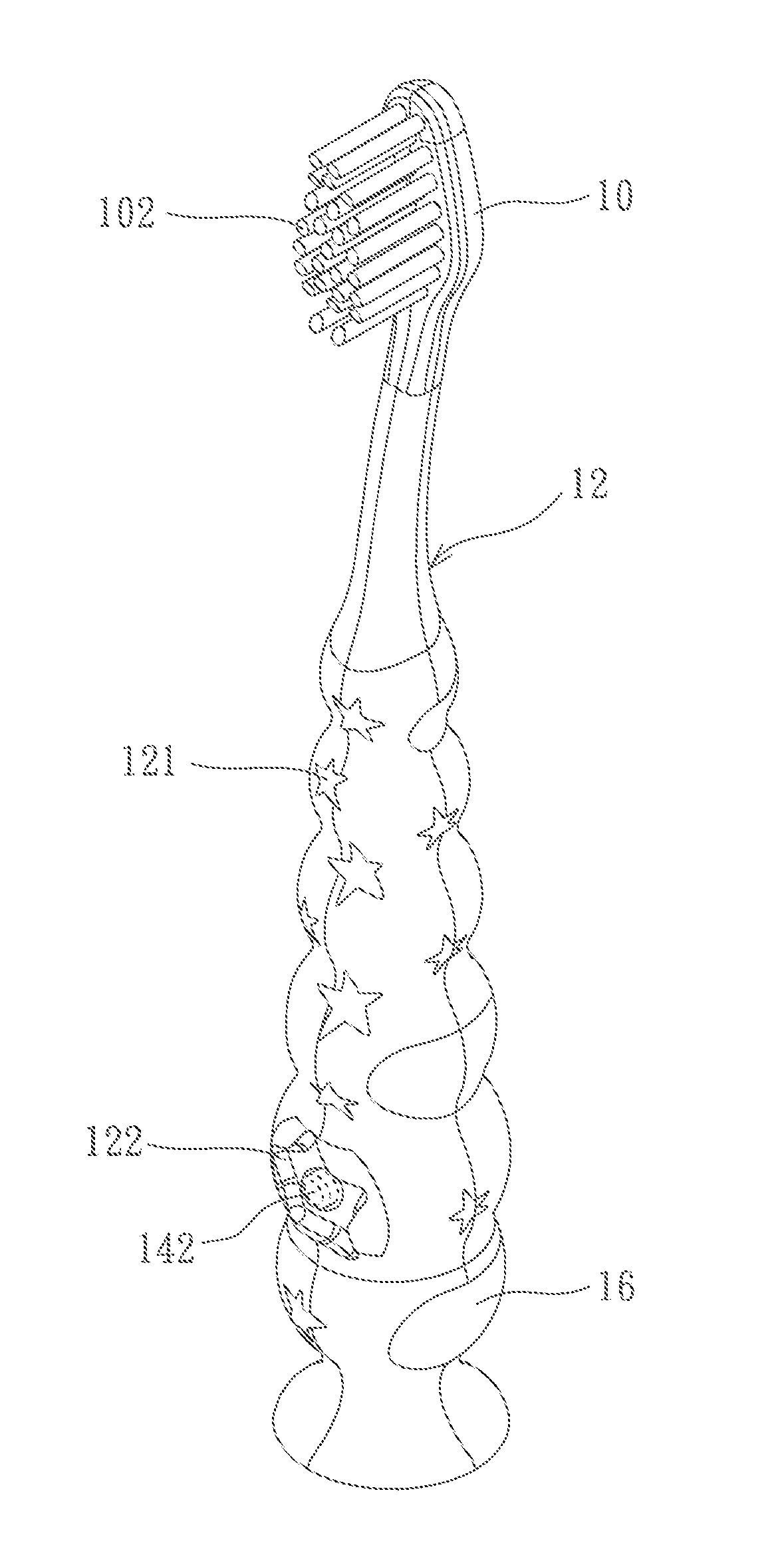
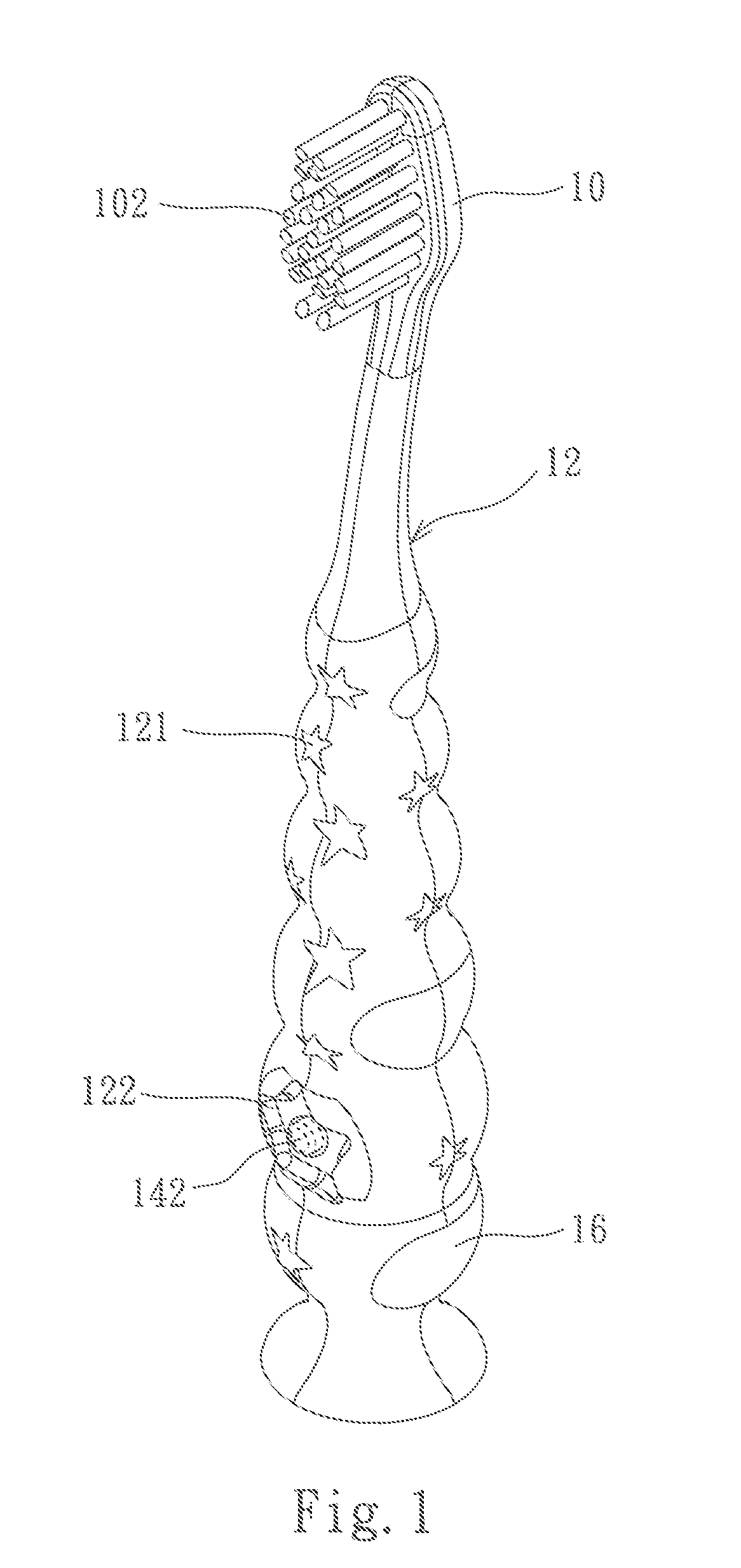
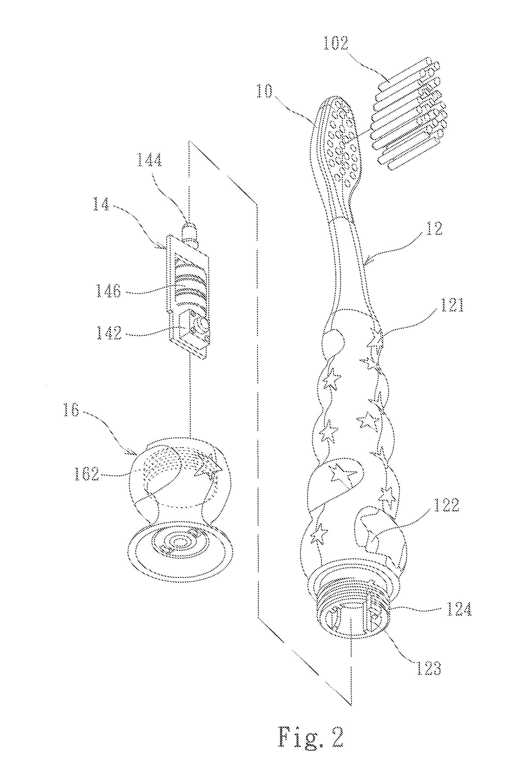
[0016]Refer to FIG. 1 and FIG. 2 which are respectively a perspective view and an exploded view of the present invention. The lighting toothbrush structure comprises a brush head 10, a hollow brush handle 12, a lighting circuit board 14, and a tail cover 16. The brush head 10 is provided with a brush set 102, The style and the material of the brush set 102 depend on the requirement for cleaning mouth. The hollow brush handle 12 is provided with a first transparent patterned layer 121 and a cavity 122. At least one slide track 123 is arranged on an inside wail of the hollow brush handle 12. A front end of the hollow brush handle 12 connects with the brush head 10. An outer edge of a rear end of the hollow brush handle 12 is provided with an outer thread 124, The lighting circuit board 14 has a switch 142 and a lighting element 144 coupled to the switch 142. In order to correspond to the long and thin shape of the hollow brush handle 12, the lighting circuit board 14 has the shape of ...


PUM


Abstract

In a lighting toothbrush structure, a front end of a hollow brush handle connects with a brush head. The hollow brush handle is provided with a first transparent patterned layer and a cavity. At least one slide track is arranged on an inside wall of the hollow brush handle. A lighting circuit board is arranged in the hollow brush handle by using the slide track. A switch is protruded from and mounted in the cavity, conveniently pressed by a user. The switch and the brush set belong to an identical side. The switch controls a lighting element to emit light, and the light is projected outside through the first transparent patterned layer. An inner thread of a tail cover is screwed to an outer thread of a rear end of the hollow brush handle to assemble the lighting toothbrush structure with a lighting function.

Description

BACKGROUND OF THE INVENTION[0001]This application claims priority for Chinese patent application no. 201320409890.2 filed at Jul. 10, 2013, the content of which is incorporated by reference in its entirely.FIELD OF THE INVENTION[0002]The present invention relates to a lighting toothbrush structure, particularly to a lighting toothbrush structure with a side thereof provided with a switch to improve operation convenience.DESCRIPTION OF THE RELATED ART[0003]Brushing the teeth is widely applied to keep the mouth clean and hygienic, removes food residues and dental plague on tooth surfaces, massages the gums, improves blood circulation, and helps tissue to improve resistance to disease. As a result, brushing can suitably protect the teeth from caries and periodontitis.[0004]Along with people living standard enhancement, the demand for cleanliness, health care and comfort of toothbrushes is higher and higher. Presently, there are all kinds of toothbrushes in the market, such as electric ...

Claims


Application Information

Patent Timeline
Patent Type & Authority Applications(United States)
IPC IPC(8): A46B15/00F21V23/02A46B9/04F21V23/04
CPCF21V23/023A46B15/0036F21V23/04A46B9/04A46B15/0087A46B15/0044F21V33/0004F21V33/004A46B17/02
Inventor LI, MING-KUEI
Owner SHUMMI ENTERPRISE
Learn More