Snap ring pliers

a technology of snap ring pliers and pliers, which is applied in the direction of pliers, metal-working hand tools, metal-working apparatus, etc., can solve the problems of snap ring to fly, snap ring to fall, and individual holding snap ring pliers to hit and hurt, so as to reduce the bent angle, stop exerting force, and the effect of less resistan

Inactive Publication Date: 2015-01-15
WANG YUAN YU
View PDF12 Cites 5 Cited by
  • Summary
  • Abstract
  • Description
  • Claims
  • Application Information

AI Technical Summary

Benefits of technology

[0008]A curved ratchet rack has one end fixedly secured to an open end of the second handle and the other end disposed proximate to an open end of the first handle. A sliding member fixedly secured to an open end of the first handle and adapted to ride on the ratchet rack. The sliding member comprises an internal channel therethrough with the other end of the ratchet rack disposed therein in an inoperative position of the pliers. The ratchet rack can move through the channel in an operative position. The sliding member has an opening at a front end thereof and a projection at a rear thereof. The projection is pivotally connected with a movable lock member, and an elastic plate is fixed on the projection. The lock member has an upper protrusion to lift the elastic plate obliquely. One end of the elastic plate is fixed on the projection, and the other end of the elastic plate is bent inward to form a hook portion extending through the opening to the channel. One side of the lock member is provided with a limit member. The limit member has a flat board extending on the surface of the lock member. The inner surface of the flat board is formed with a lower protruding stop which is away from the elastic plate. The elastic plate has a lower protrusion corresponding to the upper protrusion of the lock member. The upper protrusion holds against the lower protrusion in the inoperative position. When the upper protrusion of the lock member holds against the lower protrusion of the elastic plate to lift the elastic plate, the hook portion is moved upward and the ratchet rack is not contact with teeth. The gripping members of the jaws of the first and second lever can be operated freely by the handles to lock a snap ring between a maximum angle and a minimum angle. After the gripping members grip the snap ring, the lock member is turned for the upper protrusion to disengage from the lower protrusion of the elastic plate. The hook portion descends to enter the channel and get contact with the teeth of the ratchet rail. The stop of the limit member is moved to the upper surface of the elastic plate to block the hook portion from moving upward so that the distal end of the hook portion mates with the teeth stably. Next, the user may continuously exert force to grip the handles of the first and second levers so as to flexibly deform (i.e., expand) the snap ring. During the angle between the handles is gradually reduced, the ratchet rail is moved inward toward the channel of the sliding member. The hook portion of the elastic plate is compressed and deformed by the slope of a tooth of the ratchet rail to reduce its bent angle and then restore to be engaged with the stop surface of the next tooth, such that the ratchet rail is moved step-by-step in the channel. The snap ring is deformed by the gripping members. The user may stop exerting force on the handles when the snap ring is firmly held by the gripping members to lock or unlock the snap ring on a workpiece. After finishing the working, the lock member is turned again for the stop of the limit member to disengage from the upper surface of the elastic plate to release the hook portion. The upper protrusion holds against the lower protrusion of the plastic plate to lift the elastic plate obliquely, and the hook portion is moved upward to disengage from the teeth of the ratchet rail. The ratchet rail is released to slide backward in the channel. The first and second levers are biased by the torsion spring to return. The snap ring is restored to its original shape before deformation, so that the gripping members can disengage from the snap ring smoothly. According to the entire structure of the present invention, the lock member is simply turned to control the gripping members to hold or release deformation of the snap ring. The lock member is turned for the stop of the limit member to hold against the upper surface of the elastic plate to block the hook portion from moving upward, so that the elastic plate can be made with a thinner plate. The hook portion is flexibly held by the teeth of the ratchet rail. The lower protrusion of the elastic plate is held by the upper protrusion of the lock member with less resistance. This enhances the lock member to be turned in a labor-saving or flexible way.

Problems solved by technology

When the operation is inappropriate, the snap ring may fall before positioned.
The stored elastic energy of the deformed snap ring may cause the snap ring to fly, hit and hurt the individual who holds the snap ring pliers.
However, the operation for the lock member to hold the elastic plate upward is laborious.
If a thin elastic plate is used, the hook portion cannot be compressed or limited to cause the hook portion to bounce unexpectedly or disengagement.

Method used


Image

  • Snap ring pliers
  • Snap ring pliers
  • Snap ring pliers

Examples


Embodiment Construction

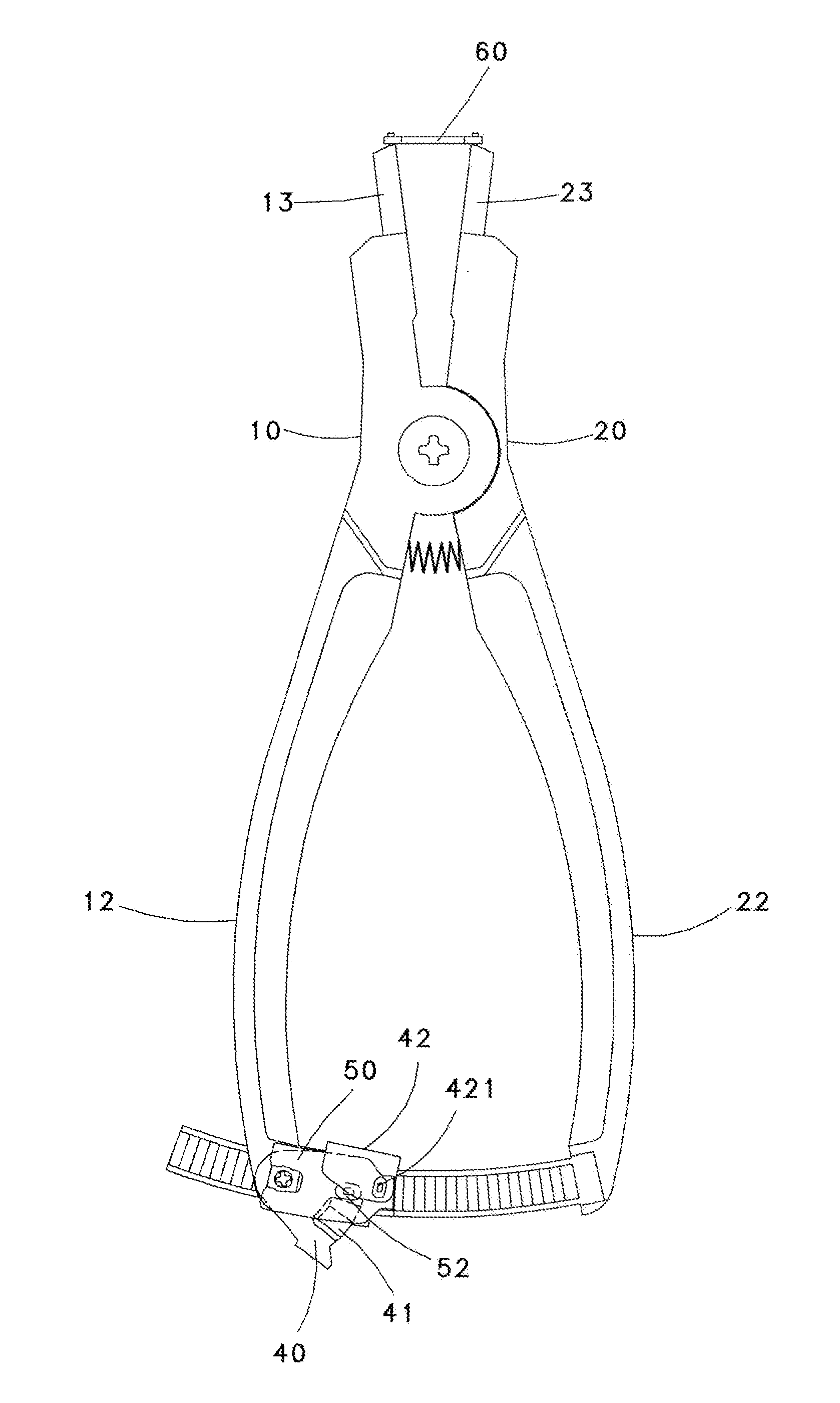
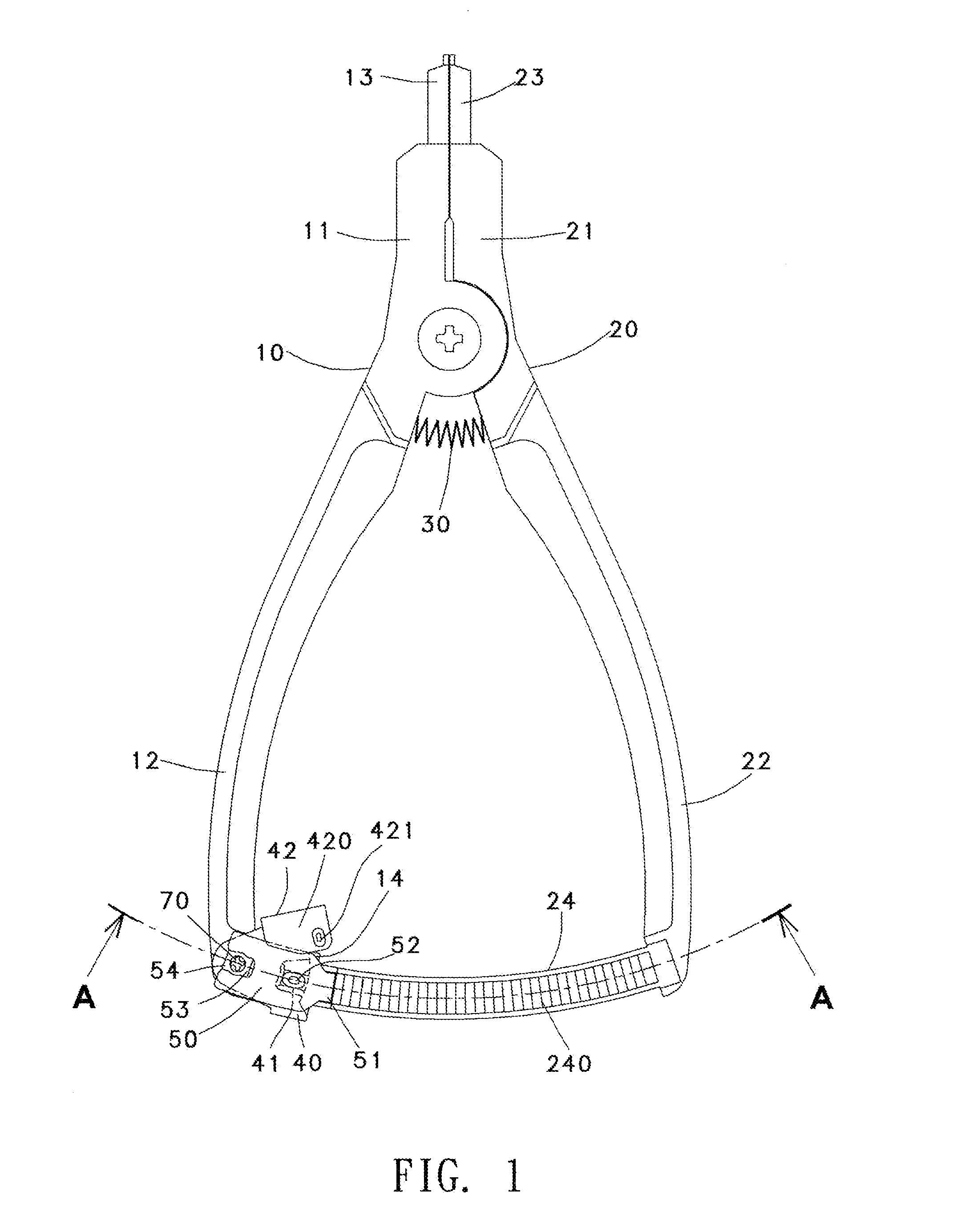
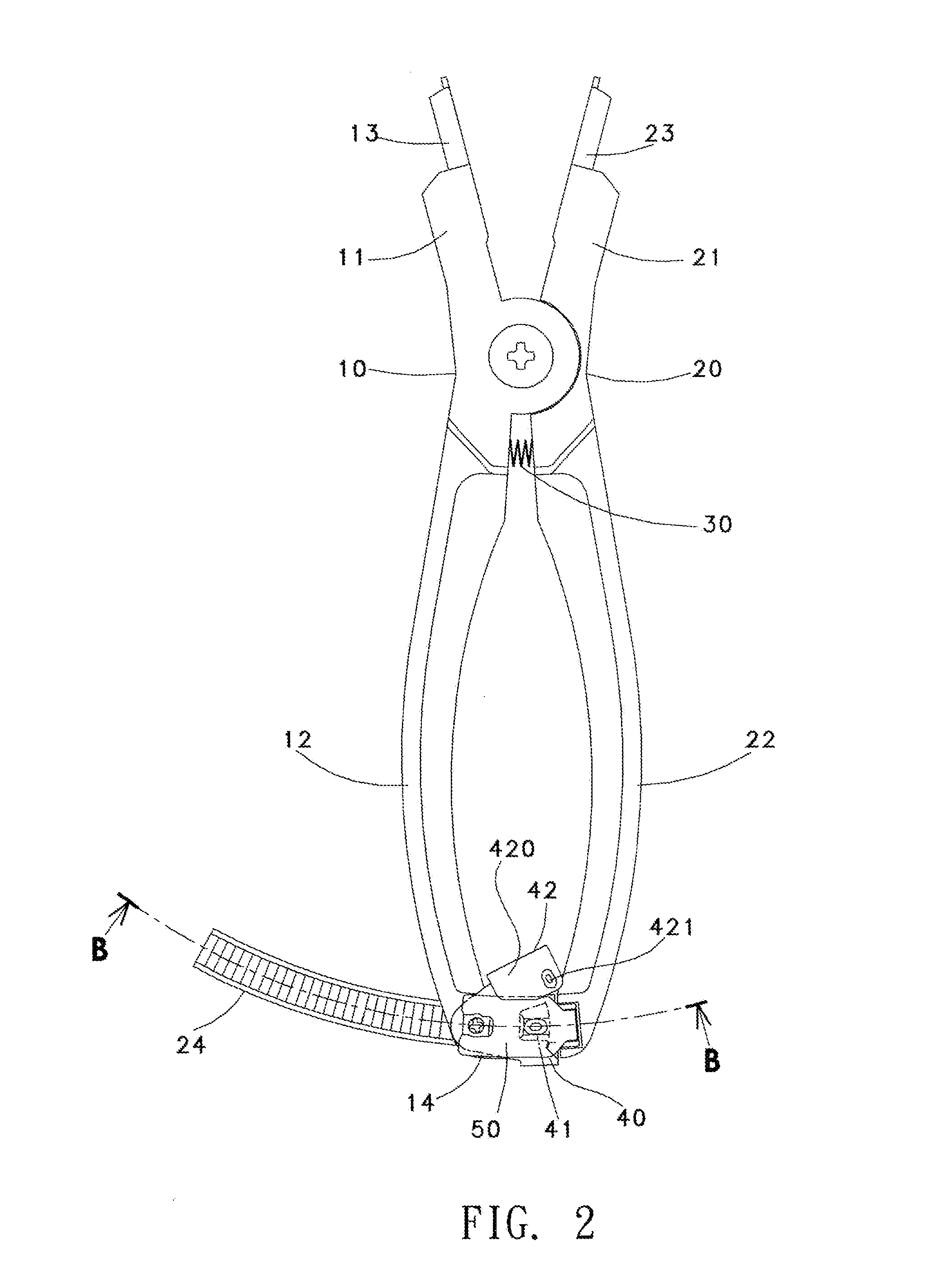
[0026]Referring to FIGS. 1 to 14, the snap ring pliers in accordance with a first preferred embodiment of the invention comprises the following components as discussed in detail below.

[0027]A pair of first and second levers 10, 20 is pivotally secured together at a fulcrum. The first lever 10 comprises a first jaw 11 and a first handle 12. The second lever 20 comprises a second jaw 21 and a second handle 22. A first gripping member 13 is projected out of an open end of the first jaw 11. A second gripping member 23 is projected out of an open end of the second jaw 21. A torsion spring 30 is provided between the first and second handles 12, 22 adjacent to the fulcrum. The first and second handles 12, 22 are operated to open or close the first and second gripping members 13, 23 by means of the torsion spring 30.

[0028]A curved ratchet rack 24 has one end fixedly secured to an open end of the second handle 22 and the other end disposed proximate to an open end of the first handle 12. A s...


PUM

PropertyMeasurementUnit
flexibleaaaaaaaaaa
elasticityaaaaaaaaaa
stored elastic energyaaaaaaaaaa

Abstract

The present invention relates to a snap ring pliers. As to the entire structure of the present invention, a lock member is simply turned to control gripping members to hold or release deformation of a snap ring. The lock member is turned for a stop of a limit member to hold against the upper surface of an elastic plate to block a hook portion from moving upward, so that the elastic plate can be made with a thinner plate. The hook portion is flexibly held by teeth of a ratchet rail. A lower protrusion of the elastic plate is held by an upper protrusion of the lock member with less resistance. This enhances the lock member to be turned in a labor-saving or flexible way.

Description

BACKGROUND OF THE INVENTION[0001]1. Field of the Invention[0002]The present invention relates to snap ring pliers, and more particularly to snap ring pliers provided with a lock member which is operated in a labor-saving flexible way.[0003]2. Description of the Prior Art[0004]A snap ring is shaped as C and used to retain elements (e.g., bearings or shafts) within a bore. The snap ring has certain elasticity itself to be expanded or contracted. In order to install the snap ring on a desired article, special pliers are required to contract or expand the snap ring so as to position the span ring on a workpiece. For conventional snap ring pliers, the user grips two handles of the pliers to operate the snap ring. The gripping members of the jaws of the pliers are opened or closed to expand or contract the snap ring. The operation is controlled by the user's feeling. That is to say, when the snap ring is contracted or expanded to a predetermined deformation, the user has to control the ex...

Claims


Application Information

Patent Timeline
Patent Type & Authority Applications(United States)
IPC IPC(8): B25B27/20B25B7/14
CPCY10T29/5363B25B27/205B25B7/14B25B7/08
Inventor WANG, YUAN YU
Owner WANG YUAN YU
Why Eureka
Try Eureka