Camshaft adjuster and stator cover unit for automatic adjustment of a locking device

a technology of automatic adjustment and camshaft, which is applied in the direction of valve details, non-fuel substance addition to fuel, air cleaners for fuel, etc., can solve the problems of increasing assembly complexity, unable to clamp and rotate the locking cover circumferentially, and relatively high manufacturing and assembly complexity, so as to achieve the effect of increasing assembly complexity and evenness

Active Publication Date: 2015-01-15
SCHAEFFLER TECH AG & CO KG
View PDF4 Cites 12 Cited by
  • Summary
  • Abstract
  • Description
  • Claims
  • Application Information

AI Technical Summary

Benefits of technology

[0010]It is an object of the present invention to eliminate these disadvantages and to provide, during assembly, a marketable locking clearance in a camshaft adjuster despite a locking cover which is unable to be directly gripped or is difficult to grip during assembly, without greatly increasing the assembly complexity—even if a restoring spring is used.

Problems solved by technology

However, the disadvantage of known stator cover units, for example in a unit known from U.S. Pat. No. 6,311,654 B1, is their relatively high manufacturing and assembly complexity.
Due to the installation space restrictions and customer specifications with regard to a driving plane, such as a belt plane, the fact that the locking cover is unable to be clamped and rotated in the circumferential direction directly via the gripper used occurs over and over again.
This problem increases in a locking cover situated axially within an offset mounted part.
A greater assembly complexity is required and, in the worst case, the desired adjuster concept may not even be implemented due to an imprecise assembly, since the locking cover is situated axially within another component, for example a belt pulley stator unit.
Assembly is made even more difficult if a restoring spring must be pretensioned with the locking cover.

Method used


Image

  • Camshaft adjuster and stator cover unit for automatic adjustment of a locking device
  • Camshaft adjuster and stator cover unit for automatic adjustment of a locking device
  • Camshaft adjuster and stator cover unit for automatic adjustment of a locking device

Examples


Embodiment Construction

[0031]The figures are only schematic and are used only for the sake of understanding the present invention. Identical elements are provided with identical reference numerals.

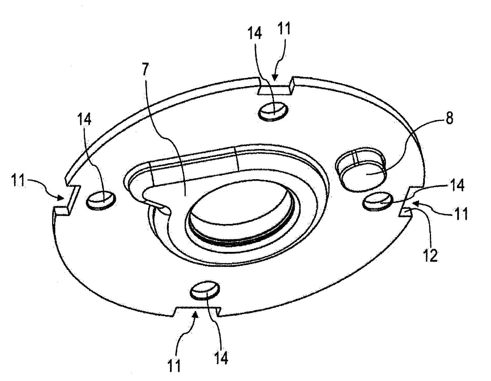
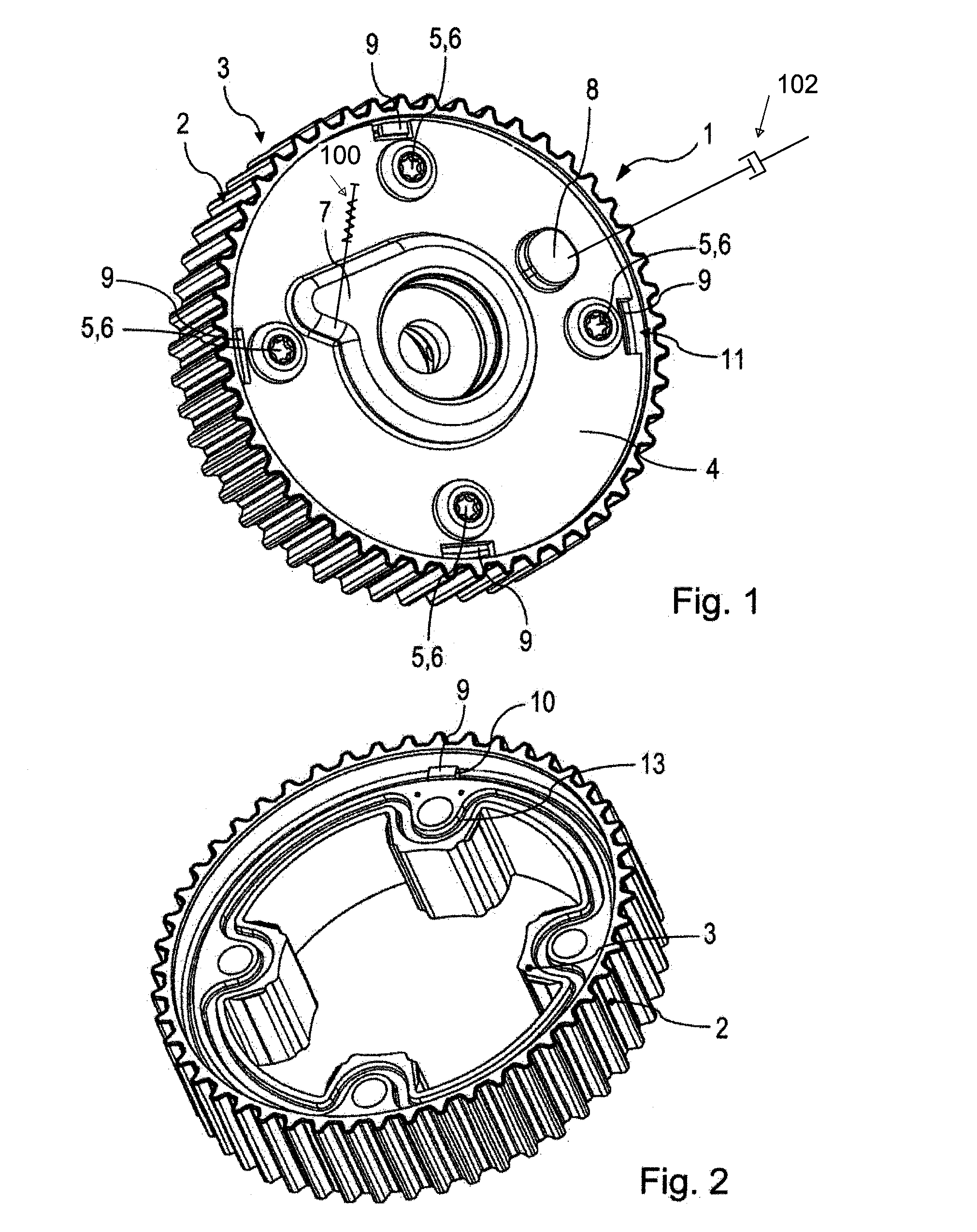
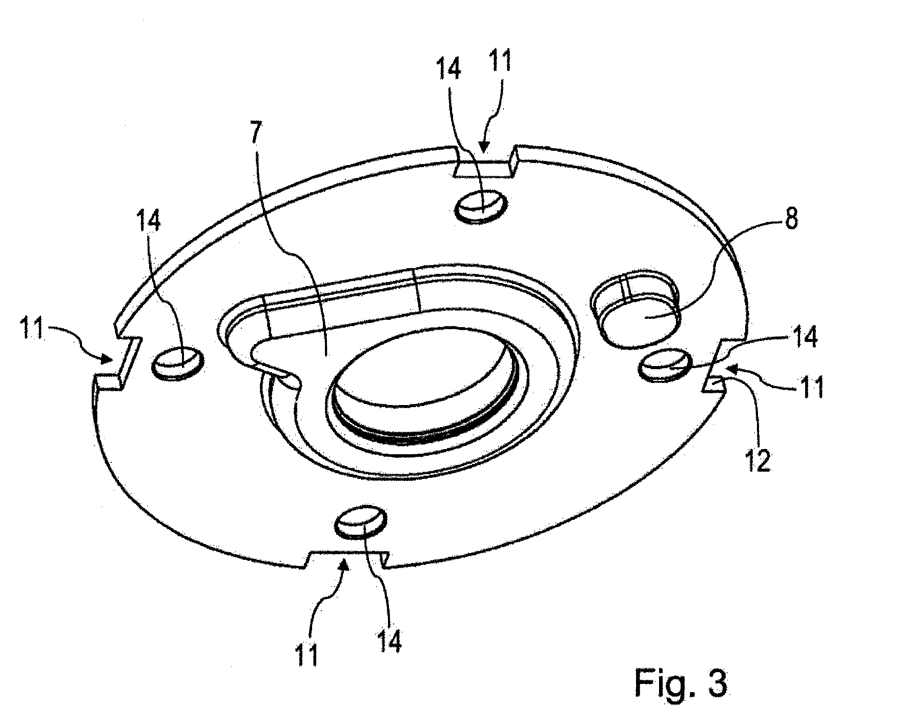
[0032]A first specific embodiment of a stator cover unit according to the present invention is illustrated in FIG. 1. This stator cover unit has reference numeral 1. The stator cover unit has an annular gear 2, a stator 3 and a locking cover 4. Locking cover 4 has a plate-like design and may also be referred to as a locking plate. Locking cover 4 is connected to a second cover, which is not illustrated, or directly to stator 3 with the aid of fastening means 5, which are designed as screws 6. A tab-like bulge 7, which provides a contact surface for a spring, is situated on the outside of locking cover 4.

[0033]A spring 100, which is illustrated solely schematically and which, in the illustration according to FIG. 1, rotatably presses locking cover 4 counterclockwise relative to stator 3, is provided within the ca...


PUM


Abstract

A stator-cover unit (1) for a camshaft adjuster designed for use in an internal combustion engine, having a toothed ring (2) for receiving a torque, there being integrally connected to said toothed ring a stator (3) in the form of a housing, having a locking cover (4) which is separate from the stator (3), wherein the locking cover (4) is connected rotationally conjointly to the stator (3), wherein the stator (3) and the locking cover (4), at least during assembly, are held rotationally conjointly secured in said position by means of a projection (9) on one of the two components, which projection engages with a form fit into a recess (11) on the other of the two components. A camshaft adjuster having a rotor and having a correspondingly designed stator-cover unit (1), wherein a piston can be introduced, movably in an axial direction, into an opening of the locking cover (4).

Description

[0001]The present invention relates to a camshaft adjuster and a stator cover unit for a camshaft adjuster, which is designed for use in an internal combustion engine, including an annular gear for receiving a torque, on which a stator designed as a housing, is integrally mounted, including a locking cover, which is separate from the stator, the locking cover being mounted torsion-proof on the stator.BACKGROUND[0002]Camshaft adjusters are known from the prior art and are used in internal combustion engines, for example in passenger cars, trucks or other land-bound vehicles. However, they may also be deployed in other air-bound or water-bound vehicles which use internal combustion engines.[0003]A device for changing the control times of gas exchange valves in an internal combustion engine is thus known from DE 10339871 A1. This publication relates to a device for changing the control times of gas exchange valves of an internal combustion engine, which is situated on the input end of ...

Claims


Application Information

Patent Timeline
Patent Type & Authority Applications(United States)
IPC IPC(8): F01L1/34F02B77/00
CPCF02B77/00F01L1/34F01L1/3442F01L2001/34469F01L2001/34479F01L2250/04F01L2303/00
Inventor BOESE, OLAFBRENNER, HOLGER
Owner SCHAEFFLER TECH AG & CO KG
Why Eureka
Try Eureka