
Bottle Stopper With A Dispensing Mechanism

a technology of dispensing mechanism and bottle, which is applied in the direction of packaging, liquid dispensing, closures, etc., can solve the problems of not creating an air-tight seal that conforms to a plurality of different types, consuming and strenuous user's dispensing of liquid from the lower portion of the bottle, and transferring contaminants from the user's hands

Inactive Publication Date: 2015-01-15
VANSYCKEL JOEL MICHAEL
View PDF21 Cites 23 Cited by
  • Summary
  • Abstract
  • Description
  • Claims
  • Application Information

AI Technical Summary

Benefits of technology

The patent is for a new invention that includes a dispensing structure tube with multiple latching surfaces. This allows the receiving structure to be securely positioned between the latching surfaces, preventing it from moving up or down the tube. The technical effect of this is that it ensures a more stable and reliable connection between the receiving structure and the rest of the system.

Problems solved by technology

Gravity fed dispensing stoppers make the dispensing of a liquid from the lower portion of a bottle time consuming and strenuous for a user when a user has to tip the bottle upside-down.
When a prior art bottle stopper is inserted into and removed from a bottle, a user grasps and pulls the dispensing tube of the bottle stopper which is unsanitary and can transfer contaminants from a user's hands to the liquid being poured from the bottle.
One challenge being the need for a bottle stopper to receive a pressurized gas while maintaining an air-tight seal with the dispensing container.
The problem with a solid rubber stopper is that they do not create an air-tight seal that conforms to a plurality of different sized bottle ports.
Prior art bottle stoppers are difficult to grasp when removing from and installing into a bottle.
The problem with the prior art container fittings is that as the tubes are installed onto the fitting, the tubes could easily slide off the fitting.
Moreover, the fittings do not allow for an air-tight seal between the tubes and the fitting.
This makes the fitting susceptible to the liquid leaking out from the bottle and contamination of foreign matter into the bottle.

Method used


Image

  • Bottle Stopper With A Dispensing Mechanism
  • Bottle Stopper With A Dispensing Mechanism
  • Bottle Stopper With A Dispensing Mechanism

Examples


Embodiment Construction

[0025]In the following detailed description of the preferred embodiments, reference is made to the accompanying drawings, which form a part hereof, and within which are shown by way of illustration specific embodiments by which the invention may be practiced. It is to be understood that other embodiments may be utilized and structural changes may be made without departing from the scope of the invention.

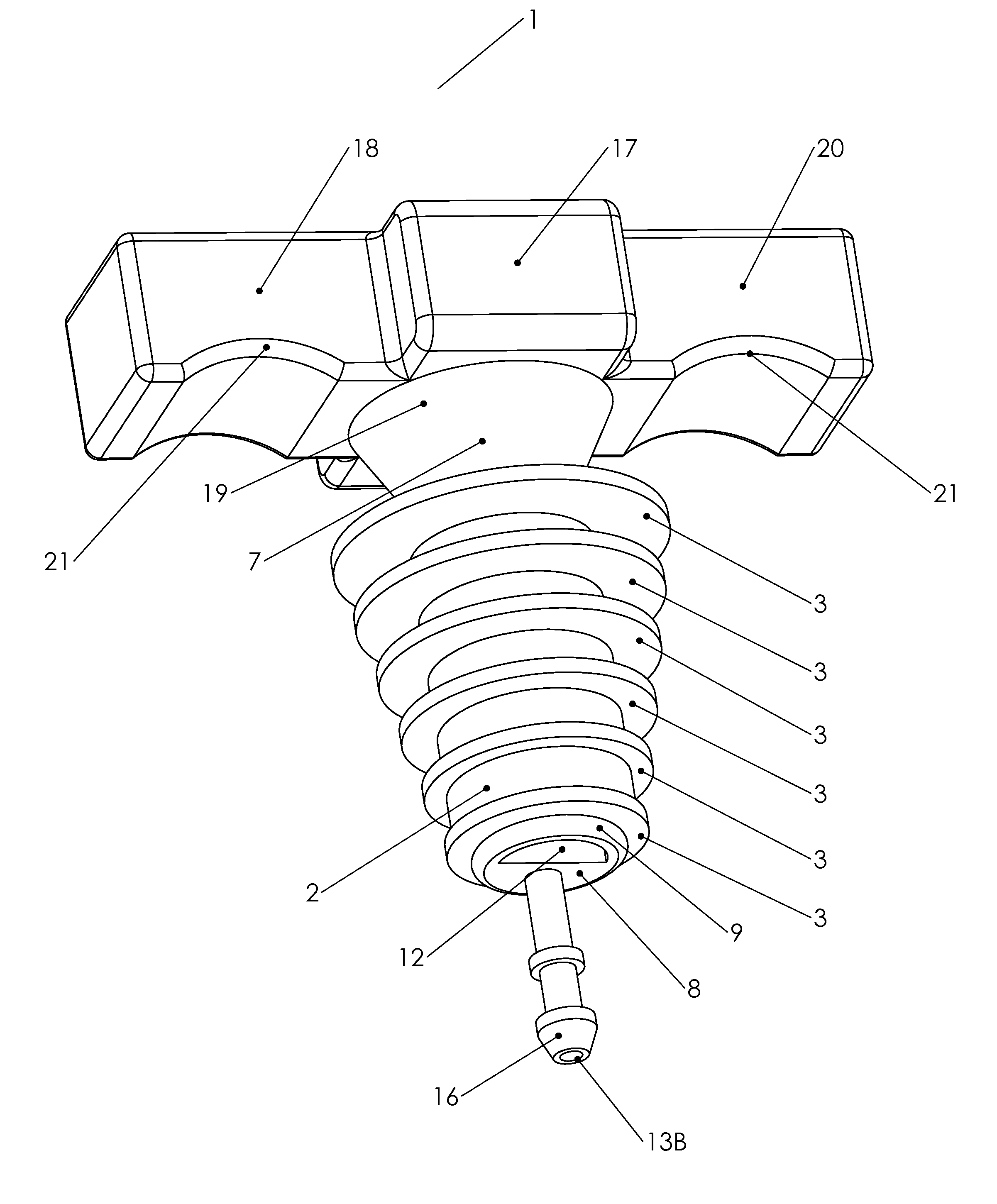
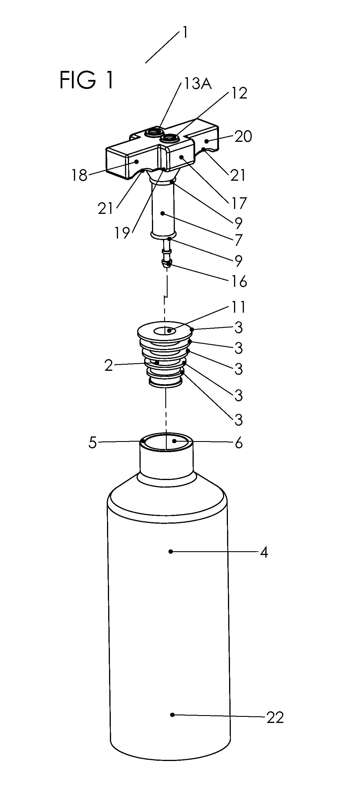
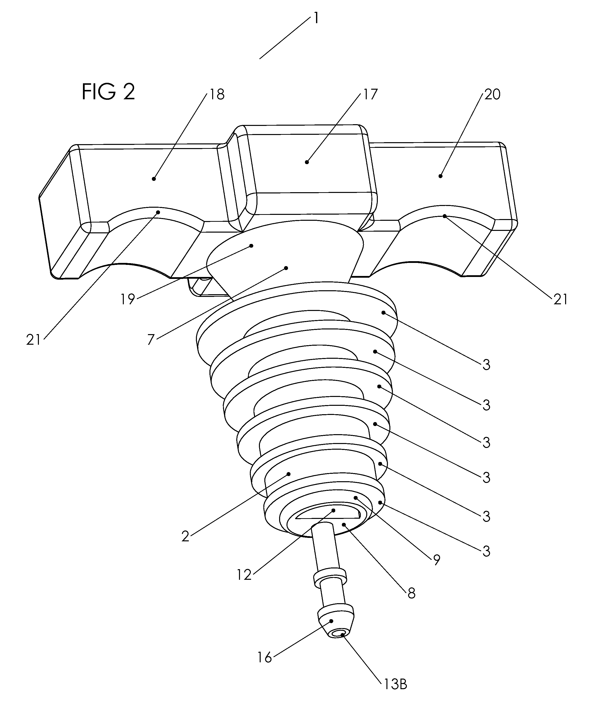
[0026]In a preferred embodiment, FIGS. 1-5 show dispensing mechanism 1 having receiving structure 2 with at least one sealing rib 3. At least one sealing rib 3 is located on a perimeter of receiving structure 2. At least one sealing rib 3 of receiving structure 2 is configured to conform to an inner wall 6 (FIG. 1) of dispensing container port 5 (FIG. 1) when at least one sealing rib 3 is inserted into dispensing container port 5 (FIG. 1). It is also within the scope of this invention for receiving structure 2 having a plurality of sealing ribs 3 located thereon. FIGS. 2 and 3 best d...


PUM


Abstract

A bottle stopper with an inlet and outlet fitting that is adapted to receive a pressurized gas to dispense a liquid from the lower portion of a bottle and having a hand grip with a dedicated arch partially conforming to at least one finger. The bottle stopper includes a dispensing mechanism having a receiving structure with at least one sealing rib configured to conform to an inner wall of a dispensing container port when the sealing rib is inserted into the dispensing container port. The receiving structure receives an end portion of a dispensing structure tube having a latching surface located on an outer perimeter of the dispensing structure tube. The primary handle structure is located opposite the secondary handle structure and they each have a dedicated arch partially conforming to a user's fingers for removing or installing the dispensing structure tube into or out of the receiving structure.

Description

BACKGROUND OF THE INVENTION[0001]1. Field of the Invention[0002]This invention relates, generally, to a bottle stopper with an inlet and outlet fitting.[0003]More particularly, it relates to a bottle stopper that is pressurized to dispense a liquid from the lower portion of a bottle.[0004]2. Background Art[0005]The bottle stoppers used in many conventional bottles are adapted to be used with bottles having a neck portion. Some bottle stoppers have a single opening that can dispense a liquid from the bottle by being gravity fed, which requires the bottle to be tipped upside-down for a liquid to exit the bottle. Gravity fed dispensing stoppers make the dispensing of a liquid from the lower portion of a bottle time consuming and strenuous for a user when a user has to tip the bottle upside-down. Moreover, gravity fed bottle stoppers have a slower rate of dispensing its liquid contents in comparison to pressurized dispensing systems. Currently, a bottle has to be within reach of a user ...

Claims


Application Information

Patent Timeline
Patent Type & Authority Applications(United States)
IPC IPC(8): B65D47/12B65D47/32
CPCB65D47/121B65D47/32B67D1/0412
Inventor VANSYCKEL, JOEL MICHAEL
Owner VANSYCKEL JOEL MICHAEL
Learn More