
Patient transport platform

a technology for transporting platforms and patients, applied in the direction of transportation and packaging, trailer steering, wheelchairs/patient conveyances, etc., can solve the problems of high cost, same difficulty in accessing patients, stretchers or platforms of a complex structure, etc., and achieve the effect of convenient movement and steering

Active Publication Date: 2015-01-15
WINCO MFG
View PDF3 Cites 24 Cited by
  • Summary
  • Abstract
  • Description
  • Claims
  • Application Information

AI Technical Summary

Benefits of technology

The invention is a patient transport platform that can easily move and steer over various floor surfaces. It is designed to lower the seat height, making it easier for patients to enter and exit. It also offers a wide range of positions and orientations to accommodate medical procedures and examinations while ensuring patient comfort. Additionally, it has an articulating base that is easy to use with a stretcher chair and can accommodate free floating and dampened actions.

Problems solved by technology

Typically, patient transport stretcher chairs have also had a lowest seat height in the range of 24 inches, making the same difficult to access by the patient.
Moreover, presently existent transport chairs that are adapted for use as treatment or medical procedure stretchers or platforms have been of a complex structure with attendant high costs.

Method used


Image

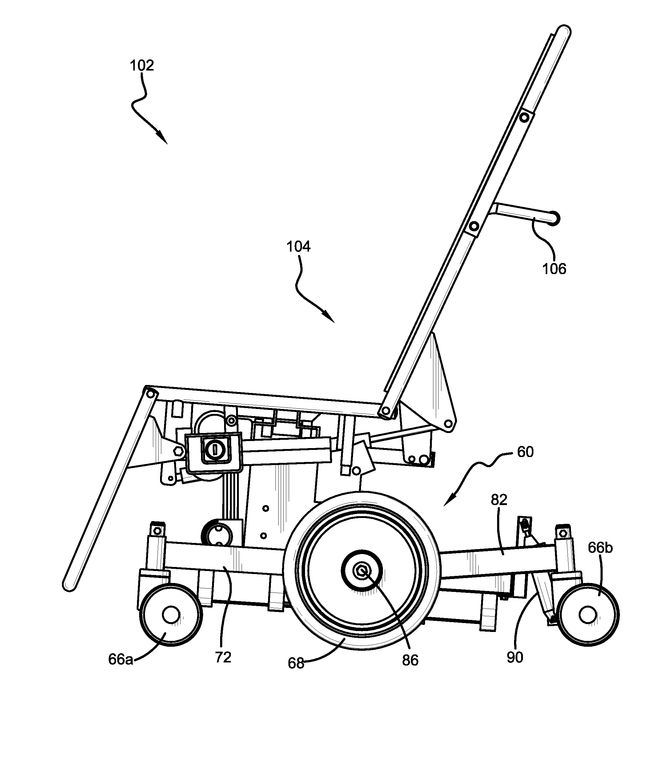
  • Patient transport platform
  • Patient transport platform
  • Patient transport platform

Examples


first embodiment

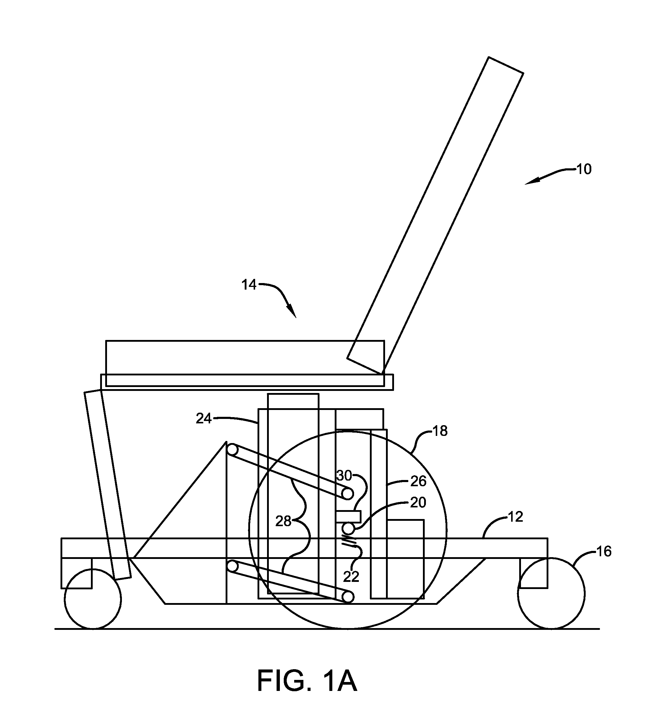
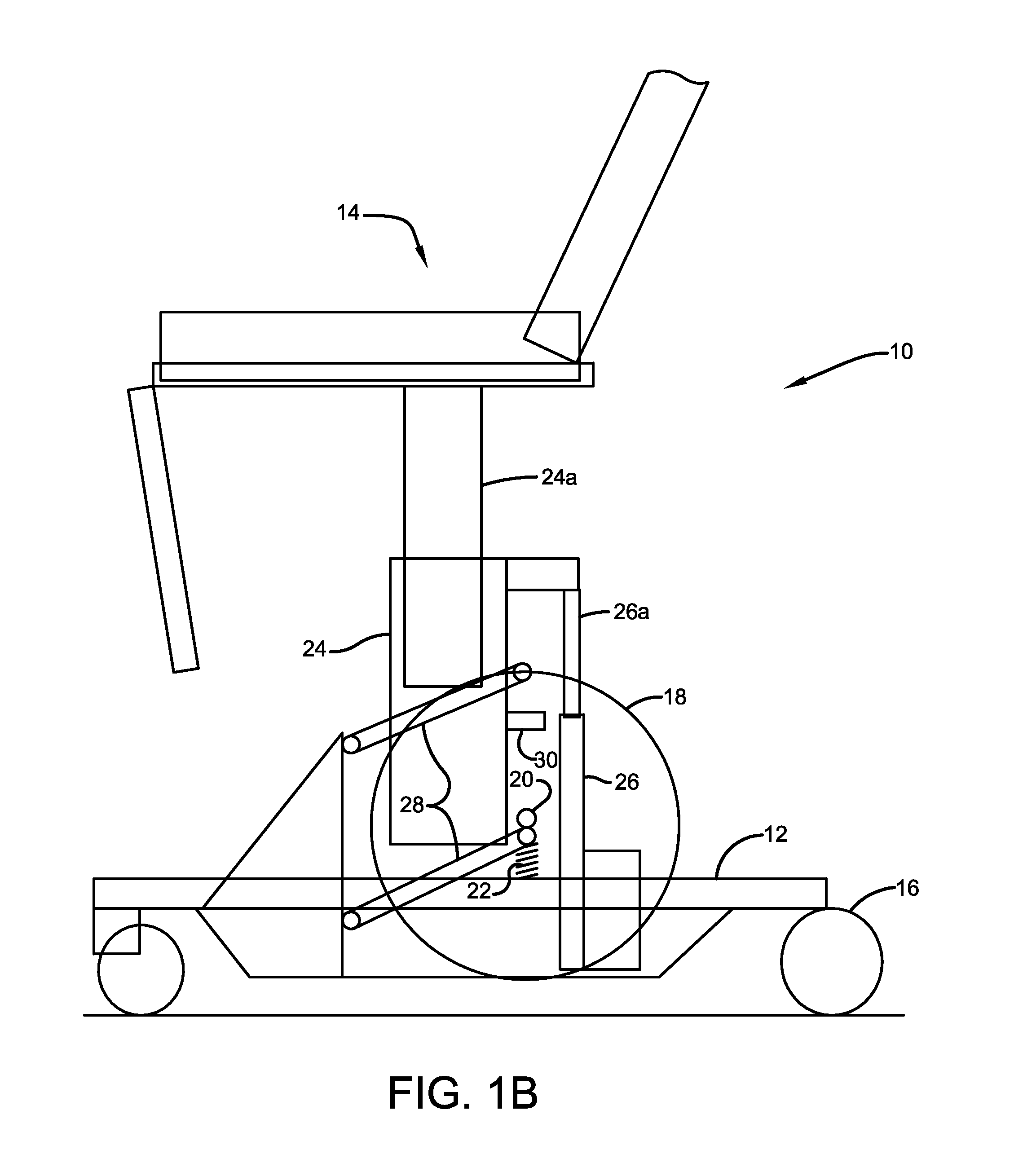
[0021]Referring now to the drawings and more particularly FIGS. 1A and 1B, an appreciation can be obtained of the structure and operation of the invention. This embodiment shows a patient transport platform wherein the height adjustment mechanism is divided into two independently controlled mechanisms operating in series. They include a typical adjustable column actuator plus a modified double wishbone suspension of the column such that it is adjusted by a separate actuator. A protrusion on the outer part of the column can rest on the axle of the large wheel in the lowered position. The double wishbone actuator has a free floating ability at the bottom of its stroke. When this actuator is raised, springs lift the wheel axle above the floor to allow movement and positioning of the patient transport device on its castors.

[0022]With specific attention to FIGS. 1A and 1B, it will be appreciated that a patient transport platform according to a first embodiment of the invention is designa...

third embodiment

[0027]With reference now to FIGS. 3A-3B, an appreciation can be attained with regard to a patient transport platform made in accordance with the invention and designated generally by the numeral 50. Here, adjustable columns 52, 54, 56 are operatively interconnected, having respective pistons 52a, 54a, and 56a. Pistons 52a and 56a are operatively connected to the stretcher chair 14, such as the seat portion, while the piston 54a is connected to the base 12. The adjustable columns and associated pistons 52, 56 are interconnected in parallel, with that combination being in series interconnection with the adjustable column 54. The adjustable column 54 has an associated stop 58, adapted for engagement with the axle 20 of the large wheels 18, as discussed above. For that purpose, the piston 54a of the adjustable column 54 is free floating at the bottom of its stroke, to accommodate movement as against the spring 22 when a patient is received within the chair.

[0028]FIG. 3A shows the patien...


PUM


Abstract

Embodiments of a patient transport platform employing one or more adjustable columns interposed between a base having caster wheels with one or more intermediate large wheels, the adjustable columns accommodating deployment and retraction of the large wheels and elevation and positioning of an articulating patient stretcher chair. In various embodiments, the adjustable columns are in parallel or series connection, or combinations thereof. An articulating base frame assembly with a dampened interconnection between fore and aft sections, having three pairs of wheels for selective implementation in use is also presented.

Description

CROSS REFERENCE TO RELATED APPLICATION[0001]This application hereby claims the benefit of and priority to U.S. Provisional Patent Application 61 / 632,775, filed Jan. 31, 2012, titled “Patient Transport Platform,” which is hereby incorporated by reference in its entirety.TECHNICAL FIELD[0002]The invention herein resides in the art of patient transport and procedure devices. More particularly, the invention relates to such devices that provide for ease of maneuverability and access by the patient, while providing a broad range of procedural utility. Specifically, the invention relates to a patient transport platform that allows for improved mobility by incorporating a set of castered wheels with an interposed pair of deployable large diameter wheels, in conjunction with a seat having a range of adjustable heights and orientations so as to accommodate ease of patient accessibility and care giver utility. Also presented is an articulated base frame assembly with a dampened interconnectio...

Claims


Application Information

Patent Timeline
Patent Type & Authority Applications(United States)
IPC IPC(8): A61G1/017A61G5/00A61G1/02A61G5/04A61G5/10
CPCA61G1/017A61G5/04A61G5/1059A61G1/0237A61G1/0275A61G5/006A61G5/00A61G2200/32A61G2200/34A61G5/043A61G7/005A61G5/1078A61G5/1089
Inventor YOUNGMANN, TREVORHUML, BRIANHEIDENREICH, DAVIDYENSHO, NATHANMASKE, MICHAEL
Owner WINCO MFG
Learn More