Infusion set that prevents air entry into infusion tubing

a technology of infusion set and infusion tube, which is applied in flow control, non-electric variable control, intravenous devices, etc., can solve the problems of air embolism, hospitalization will incur additional treatment costs, sudden loss of consciousness, etc., and achieve the effect of safe replacement of the infusion bottl

Inactive Publication Date: 2015-01-15
WELFORD MFG M
View PDF6 Cites 29 Cited by
  • Summary
  • Abstract
  • Description
  • Claims
  • Application Information

AI Technical Summary

Benefits of technology

[0021]According to a second aspect of the present invention, there is provided an infusion set (10) characterized in that there is provided a clip (50) located between the drip chamber (20) and the roller clamp (60). When the clip (50) is closed, no air bubbles will pass thr

Problems solved by technology

Various problems are associated with infusion devices with or without air stop membrane.
One of the problems commonly found in normal infusion devices without air stop membrane is that certain amount of air in the form of bubbles often gets into the blood circulation accidentally during the infusion procedure and which will lead to air embolism.
Depending on the size of such air embolism, various complications suffered by the patient may include chest pain, wheezing, breathlessness, stroke, tachycardia (fast heart beat), sudden loss of consciousness leading to death, etc.
Besides facing possible negligence claims brought against the hospitals by the patients, more commonly, hospitals will incur additional treatment cost in the case of complication due to air embolism.
(a) Improper priming of the infusion line at the start of the infusion procedure;
(b) During the infusion process itself, due to the fast dripping of the liquid;
(c) When the infusion bottle runs empty and the infusion process is not stopped; and
(d) When the infusion set is placed improperly or at a slant position during an emergency.
This practice of manually pushing out the air bubbles in the infusion tube takes up much of the medical staff time.
In case where re-priming is needed, it also i

Method used


Image

  • Infusion set that prevents air entry into infusion tubing
  • Infusion set that prevents air entry into infusion tubing
  • Infusion set that prevents air entry into infusion tubing

Examples


Embodiment Construction

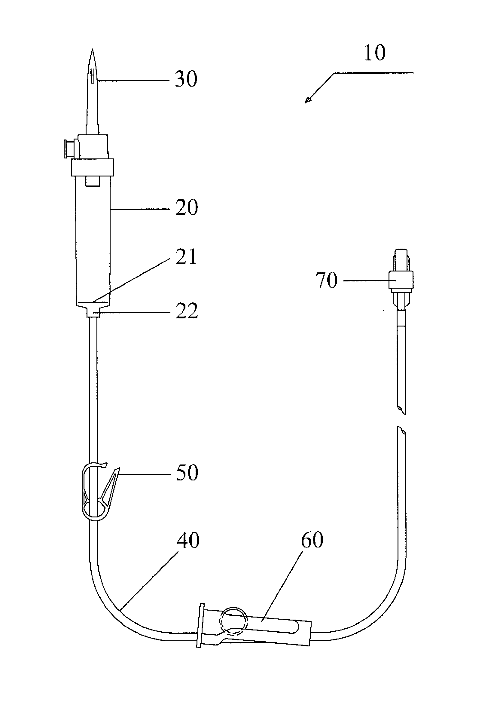
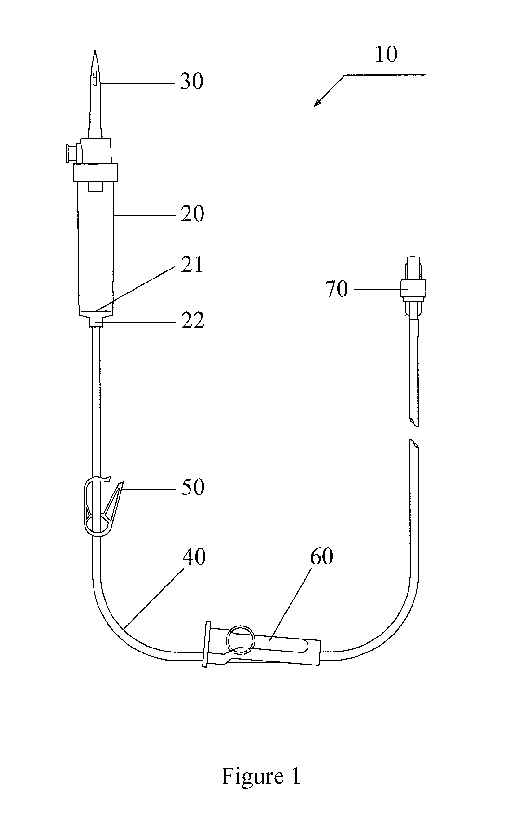
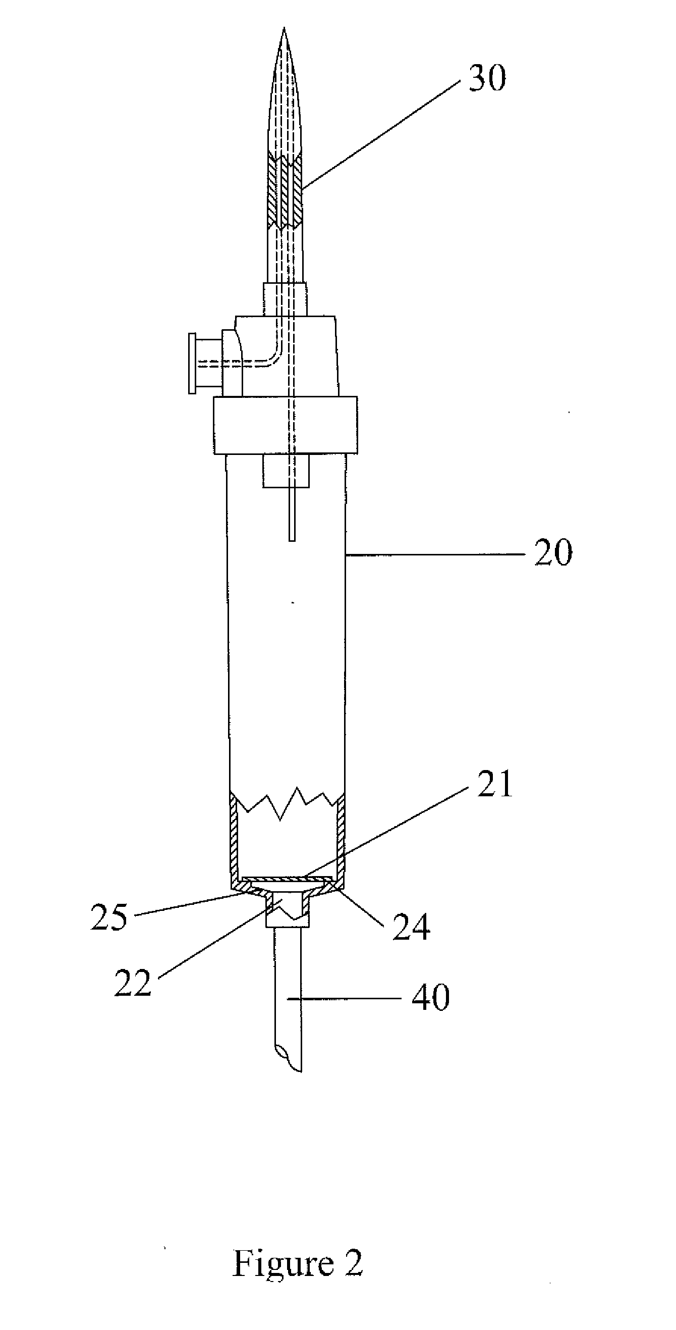
[0027]As shown in FIG. 1, the infusion set (10) comprises a drip chamber (20), said drip chamber (20) has a spike (30) on the upper end and a hydrophilic membrane (21) at its lower end, an infusion tubing (40) of sufficient length connecting the lower end of the drip chamber (20) to a standard connector (70), a roller clamp (60) is located between the drip chamber (20) and the standard connector (70), and a clip (50) is located between the drip chamber (20) and the roller clamp (60) along the length of the infusion tubing (40).

[0028]Referring to FIG. 1, an infusion line (40) is connected to the drip chamber (20). At the patient end of the infusion line, a standard connector (70) is provided so that a needle or a catheter could be connected to the patient. A flow adjustment device in the form of a roller clamp (60) is provided in the infusion line. The roller clamp (60) could be gradually adjusted so that the infusion tube could be squeezed proportionally to change the infusion rate....


PUM


Abstract

The present invention relates to an infusion set (10) that provides for continuous air free delivery of liquid to patients undergoing infusion procedures. In particular, the invention provides for an infusion set (10) that prevents air entering the infusion tubing (40) through the drip chamber (20) by using a hydrophilic membrane (21) having a defined wetting time and a defined mean pore size that will provide a defined bubble pressure point under gravitational pull to permit continuous air free infusion liquid flow there-through. The invention further provides for a clip (50) that once closed, no air bubble is able to pass through the hydrophilic membrane (21) due to the adjustment of the roller clamp (60) along the infusion tubing (40) thereby ensuring safe replacement of the infusion bottle during multiple infusion procedures, thus preventing the occurrence of air embolism in patients especially when the drip chamber (20) is empty.

Description

TECHNICAL FIELD[0001]The present invention relates to an infusion set that provides for continuous air free delivery of liquid to patients undergoing infusion procedures. In particular, the invention provides for an infusion set that prevents air entering the infusion tubing through the drip chamber by using a hydrophilic membrane having a defined wetting time and a defined mean pore size that will provide a defined bubble pressure point under gravitational pull to permit continuous air free infusion liquid flow there-through. The invention further provides for a clip that once closed, no air bubbles is able to pass through the hydrophilic membrane due to the adjustment of the roller clamp along the infusion tubing thereby ensuring safe replacement of the infusion bottle during multiple infusion procedures, thus preventing the occurrence of air embolism in patients especially when the drip chamber is empty.BACKGROUND[0002]Intravenous infusion procedure is commonly used in hospital t...

Claims


Application Information

Patent Timeline
IPC IPC(8): A61M5/38A61M5/168A61M5/14
CPCA61M5/38A61M5/1411A61M5/16813A61M5/162
Inventor WONG, THEAN FOOKWONG, WEN WVEI
Owner WELFORD MFG M
Why Eureka
Try Eureka