Method for manufacturing of urinary catheters

a manufacturing method and technology for urinary catheters, applied in the field of catheters, can solve the problems of reducing affecting the quality of the catheter, so as to achieve the effect of increasing the volume of the molding cavity

Inactive Publication Date: 2015-01-15
ROLSTED MOLD SYST APS
View PDF0 Cites 2 Cited by
  • Summary
  • Abstract
  • Description
  • Claims
  • Application Information

AI Technical Summary

Benefits of technology

[0009]Accordingly, the present invention preferably seeks to mitigate, alleviate or eliminate one or more of the above-identified deficiencies in the art and disadvantages singly or in any combination and solves at least the above mentioned problems by providing a method for manufacturing an elongated element, comprising the steps of: arranging a molding cavity, defined by a mold a mold insert, said mold insert comprising a mold core and a displaceable mold cavity wall, said displaceable mold cavity wall being arranged between the mold and the mold core, such that the molding cavity has a start volume in a start position of the displaceable mold cavity wall; injecting a liquid material into a proximal end of the molding cavity; displacing the displaceable mold cavity wall, in relation to and along with the mold and the mold core, distally during said injection, to increase the molding cavity volume from the start volume into an end volume at an end position of the displaceable mold cavity wall, wherein the molding cavity in said end position of said displaceable mold cavity wall corresponds to the elongated element; solidifying said liquid material, such that the elongated element is formed; removing said elongated element and mold insert from said mold; and removing said elongated element from said mold insert.

Problems solved by technology

The use of permanent or long-term catheters is usually linked to an individual's hospital stay or at least where the individual is under regular observation of medical professionals, as permanent catheters are not well adapted for self catheterization since they are usually very flexible and have a larger diameter than intermittent catheters.
Injection molding of urinary catheters is however accompanied with several obstacles.
Due to the delicate dimensions of a urinary catheter, such as small tube diameter and wall thickness while being relatively long, also the mold insert / core, forming the lumen of the tubular portion, needs to be thin and long.
When the molten plastic material enters the molding cavity, often under high pressure, the plastic material will whirl in the cavity.
This renders the separation of the molded catheter and the insert / core almost impossible, naturally resulting in useless manufacturing in an industrial scale.
Additionally, even though the stabilization of the insert / core helps the formation of a tubular wall with unitary dimensions, it may be very difficult to separate the insert / core from the molded catheter, due to the large contact surface between the insert / core and the plastic material.
This problem is specifically significant when the injected material is a plastic material with high adherence properties, which is often the case with plastic materials with well-suited flexibility properties for the intended purpose.

Method used


Image

  • Method for manufacturing of urinary catheters
  • Method for manufacturing of urinary catheters
  • Method for manufacturing of urinary catheters

Examples


Embodiment Construction

[0018]The following description focuses on an embodiment of the present invention applicable to an elongated element, and in particular to a urinary catheter, and more specifically an intermittent urinary catheter. However, it will be appreciated that the invention is not limited to this application but may be applied to many other elongated elements, such as Foley catheters or test tubes, etc.

[0019]In the context herein the terms “proximal” and “distal”, and analogues thereof, are used in relation to body on which the end product is to be used, while the terms “lateral” and “central” are used in relation to the longitudinal as well as the proximodistal extension of the end product. This means that also with respect of molds and mold assemblies these terms are used in relation to the end product characteristics.

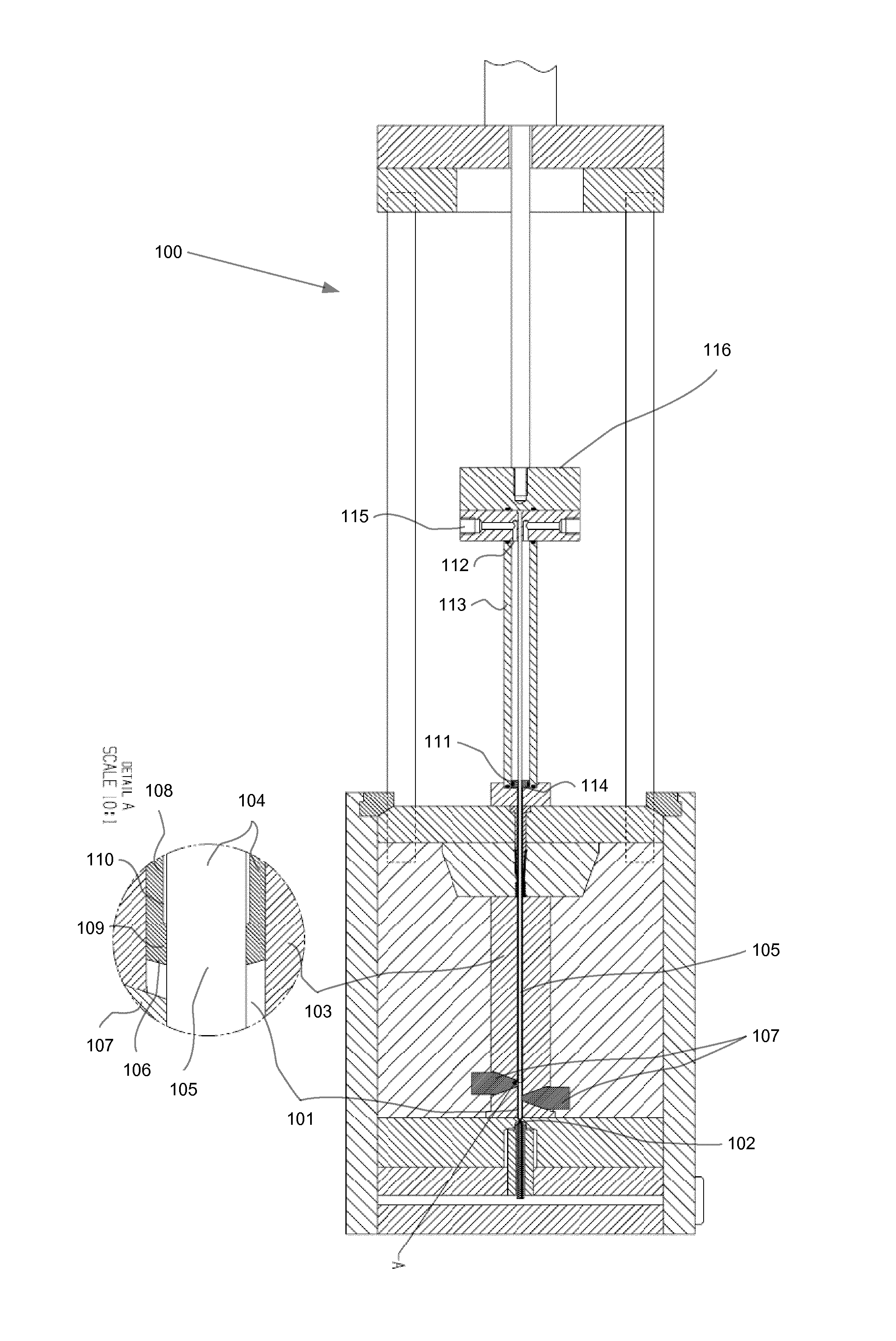
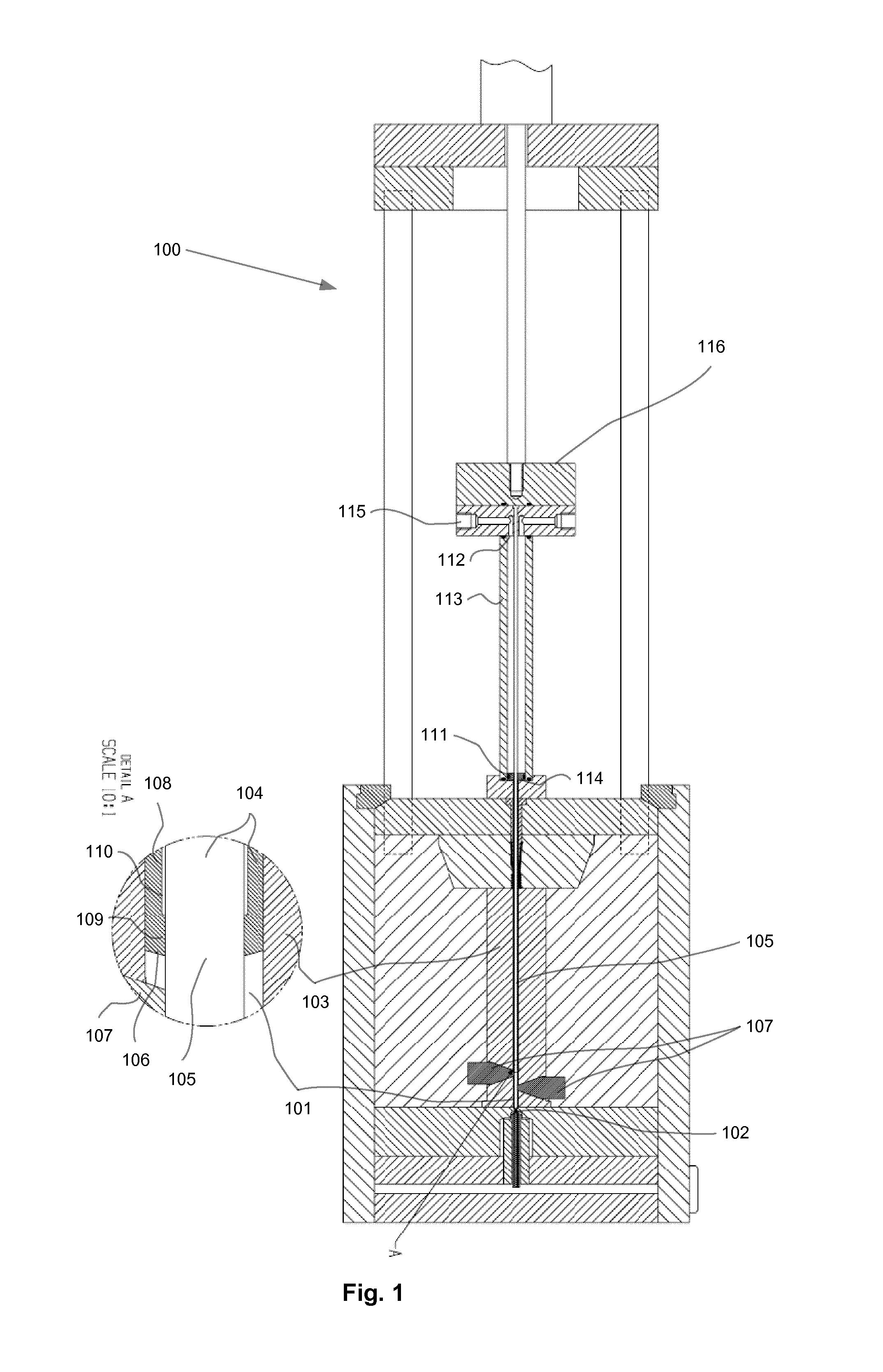
[0020]In FIG. 1 a mold assembly 100 for the manufacturing of a urinary catheter, according to an embodiment is disclosed. FIG. 1 illustrates a start position for the manufact...


PUM

PropertyMeasurementUnit
angleaaaaaaaaaa
volumeaaaaaaaaaa
cylindrical outer shapeaaaaaaaaaa

Abstract

A method for manufacturing an elongated element (200) is provided. The method comprises arranging a molding cavity (101), defined by a mold (103) and a mold insert (104), said mold insert (104) comprising a mold core (105) and a displaceable mold cavity wall (106), said displaceable mold cavity wall (106) being arranged between the mold (103) and the mold core (105), such that the molding cavity has a start volume in a start position of the displaceable mold cavity wall (106). Then a liquid material is injected into a proximal end (102) of the molding cavity (101), where after the displaceable mold cavity wall (106) is displaced in relation to and along with the mold (103) and the mold core (105), distally during said injection, to increase the molding cavity volume from the start volume into an end volume at an end position of the displaceable mold cavity wall (106), wherein the molding cavity (101) in said end position of the displaceable mold cavity wall (106) corresponds to the elongated element (200). The liquid material is solidified, such that the elongated element (200) is formed, and the elongated element (200) and mold insert (104) is removed from said mold (103), where after the elongated element (200) is removed from said mold insert (104). An elongated element and a mold assembly for the manufacture thereof are also provided.

Description

FIELD OF THE INVENTION[0001]This invention pertains in general to the field of injection molding of thin-walled, elongated, elements, with a tubular body and an optionally substantially closed end. More particularly the invention relates to a catheter, such as a urinary catheter, with an elongated tubular portion and a tip portion. Furthermore, the present invention pertains to a method of manufacturing such elements and catheters, and an assembly for forming a molding cavity.BACKGROUND OF THE INVENTION[0002]Urinary catheters are widely used by persons who have problems with respect to unintentional / intentional emptying of the urinary bladder. A wide variety of different types of urinary catheters is available to individuals or medical professionals, which are specifically designed for a specific use, such as intermittent catheters or permanent / long term catheters, such as Foley catheters.[0003]Intermittent catheters are for example used by individuals who are paralyzed, where the u...

Claims


Application Information

Patent Timeline
Patent Type & Authority Applications(United States)
IPC IPC(8): B29C45/04A61M39/10B29C45/40A61M25/00B29C45/26B29C45/36
CPCB29C45/36A61M25/0068B29C45/2616A61M25/0017A61M25/0021B29K2075/00A61M25/0009B29C45/04B29C45/40A61M39/10B29L2031/7542B29C2045/4068B29C45/261B29C45/2628B29C45/43B29C45/56B29C2045/5695
Inventor ROLSTED, ERIK
Owner ROLSTED MOLD SYST APS
Why Eureka
Try Eureka