Blade control device, working machine and blade control method

a blade control and working machine technology, applied in agricultural machines, applications, instruments, etc., can solve the problem of inevitably forming continuous undulations on the digging surfa

Inactive Publication Date: 2015-01-15
KOMATSU LTD
View PDF0 Cites 27 Cited by
  • Summary
  • Abstract
  • Description
  • Claims
  • Application Information

AI Technical Summary

Benefits of technology

[0016]According to the present invention, it is possible to provide a blade control device whe...

Problems solved by technology

JP-A-H07-54374 has a drawback that continuous u...

Method used


Image

  • Blade control device, working machine and blade control method
  • Blade control device, working machine and blade control method
  • Blade control device, working machine and blade control method

Examples


Embodiment Construction

[0026]A bulldozer will be hereinafter explained as an example of “working machine” with reference to the drawings. In the following explanation, “up”, “down”, “front”, “rear”, “left” and “right” are terms defined with reference to an operator seated on an operator seat.

Overall Structure of Bulldozer 100

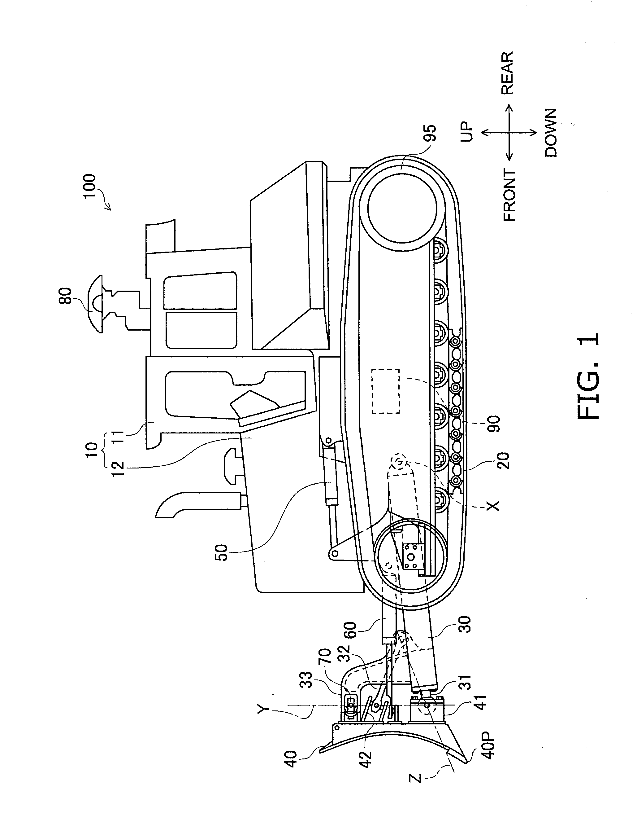
[0027]FIG. 1 is a side view of an entire structure of a bulldozer 100.

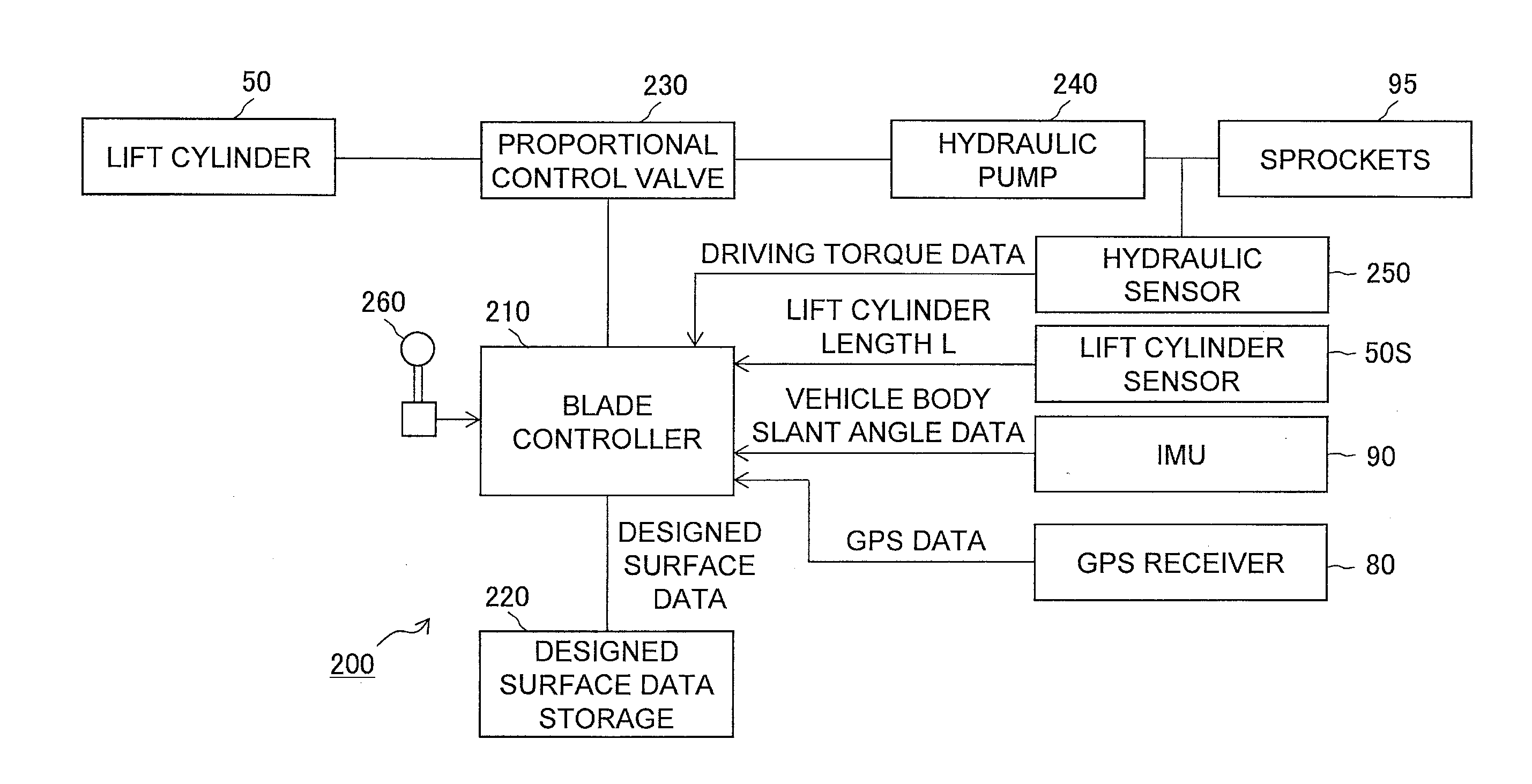
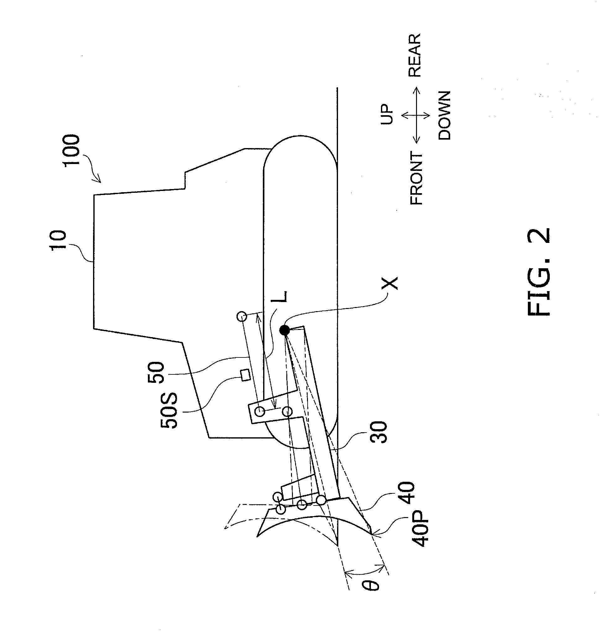
[0028]The bulldozer 100 includes a vehicle body 10, a driving unit 20, a lift frame 30, a blade 40, a lift cylinder 50, an angle cylinder 60, a tilt cylinder 70, a GPS receiver 80, an IMU (Inertial Measurement Unit) 90 and a pair of sprockets 95. Further, the bulldozer 100 is embedded with a blade control device 200 (see FIG. 3). A structure and an action of the blade control device 200 will be described below.

[0029]The vehicle body 10 includes a cab 11 and an engine compartment 12. The operator seat and a variety of operating devices (which are not illustrated in the figures) are installed inside the cab 11. The en...


PUM


Abstract

When a blade load is reduced from a value greater than or equal to a first set load value to a value less than the first set load value, a blade control device is configured to set a virtual designed surface to be closer to a blade than a designed surface is, and is configured to allow the blade to pivot above the virtual designed surface.

Description

CROSS-REFERENCE TO RELATED APPLICAIONS[0001]This application claims priority to Japanese Patent Application No. 2012-236465 filed on Oct. 26, 2012. This application is a U.S. National stage application of International Application No. PCT / JP2012 / 080015 filed on Nov. 20, 2012.FIELD OF THE INVENTION[0002]The present invention relates to a blade control device for controlling the height of a blade, a working machine and a blade control method.BACKGROUND INFORMATION[0003]Working machines have been widely used so far, which are equipped with a blade as a work implement in use for digging and leveling the ground, transporting earth and sand, and so forth. Further, a method has been proposed for automatically regulating the height of the blade in such a working machine so that a blade load acting on the blade can fall in a target range (see Japan Laid-open Patent Application Publication No. JP-A-H07-54374).SUMMARY[0004]However, according to the method described in Japan Laid-open Patent Ap...

Claims


Application Information

Patent Timeline
IPC IPC(8): E02F3/84E02F3/76
CPCE02F3/7609E02F3/844E02F3/845
Inventor HAYASHI, KAZUHIKOSHIMADA, KENJIROOKAMOTO, KENJI
Owner KOMATSU LTD
Why Eureka
Try Eureka