Computer system and virtual network visualization method

a computer system and virtual network technology, applied in the field of computer system and visualization method of computer system, can solve the problem of not being able to perform centralized monitoring of the status of the whole virtual tenant network “vtn1”

Inactive Publication Date: 2015-01-15
NEC CORP
View PDF28 Cites 93 Cited by
  • Summary
  • Abstract
  • Description
  • Claims
  • Application Information

AI Technical Summary

Problems solved by technology

It has been, however, impossible to perform centralized monitoring of the status of the whole of the virtual tenant network “VTN1”, since the two virtual networks “VNW1” and “VNW2” cannot be unified.

Method used


Image

  • Computer system and virtual network visualization method
  • Computer system and virtual network visualization method
  • Computer system and virtual network visualization method

Examples


Embodiment Construction

[0026]In the following, a description is given of exemplary embodiments of the present invention with reference to the attached drawings. The same or similar reference numerals denote the same, similar or equivalent components in the drawings.

(Computer System Configuration)

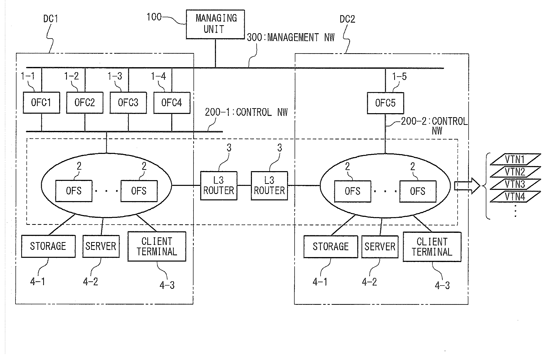
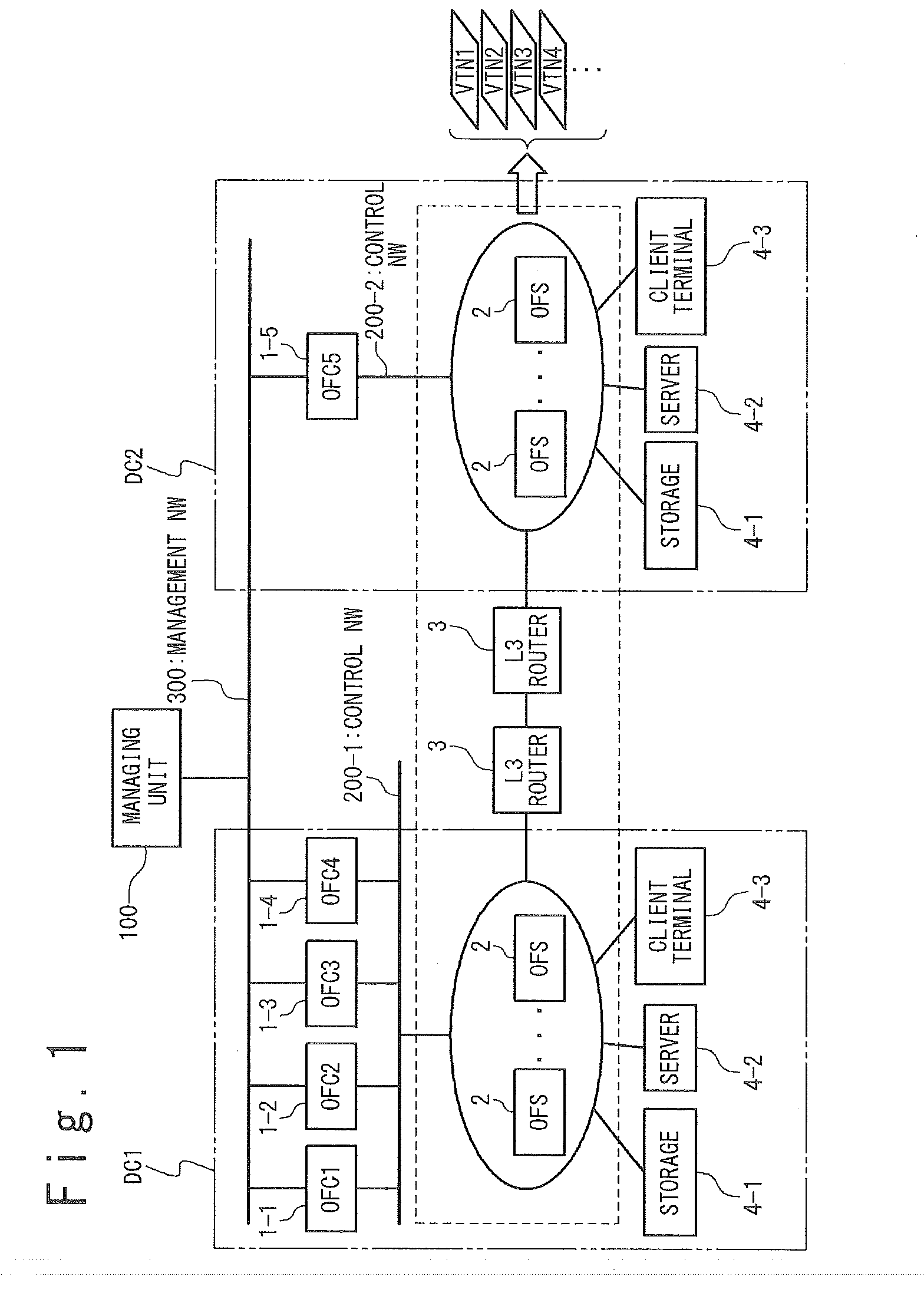
[0027]The configuration of a computer system according to the present invention is described with reference to FIG. 1. FIG. 1 is a diagram illustrating the configuration of a computer system according to the present invention in an exemplary embodiment. The computer system according to the present invention uses OpenFlow to perform establishment of communication routes and transfer control of packet data. The computer system according to the present invention includes: OpenFlow controllers 1-1 to 1-5 (hereinafter, referred to as OFCs 1-1 to 1-5), a plurality of OpenFlow switches 2 (hereinafter, referred to as OFSs 2), a plurality of L3 routers 3, a plurality of hosts 4 (e.g., storages 4-1, servers 4-2 and client t...


PUM


Abstract

A computer system according to the present invention includes a managing unit which outputs a plurality of virtual networks managed by a plurality of controllers in a visually perceivable form with the plurality of virtual networks combined, on the basis of topology data of the virtual networks, the topology data being generated based on communication routes. This enables centralized management of the whole of a virtual network controlled by a plurality of controllers which use an OpenFlow technology.

Description

TECHNICAL FIELD[0001]The present invention relates to a computer system and a visualization method of a computer system, more particularly, to a virtual network virtualization method of a computer system which uses an OpenFlow (also referred to as programmable flow) technology.BACKGROUND ART[0002]Conventionally, packet route determination and packet transfer from the source to the destination have been achieved by a plurality of switches provided on the route. In a recent large-sized network such as a data center, the network configuration is being continuously modified due to halts of devices caused by failures or additions of new devices for scale expansion. This has necessitated flexibility for promptly adapting to the modification of the network configuration to determine appropriate routes. It has been, however, impossible to perform a centralized control and management of the whole network, since the route determination programs installed on the switches have been unable to be...

Claims


Application Information

Patent Timeline
Patent Type & Authority Applications(United States)
IPC IPC(8): H04L12/759H04L12/721H04L45/28H04L45/42
CPCH04L45/14H04L45/028H04L41/0896H04L12/4641H04L12/4625H04L12/6418H04L41/22H04L41/122H04L41/12
Inventor MASUDA, TAKAHISA
Owner NEC CORP
Why Eureka
Try Eureka