Optical pressure sensor

a pressure sensor and optical technology, applied in the field of optical pressure sensors, can solve the problems of reducing the sensitivity and the range of measurement, affecting the accuracy of measurement, so as to achieve more accurate temperature compensation and improve the effect of temperature compensation

Active Publication Date: 2015-01-22
OXSENSIS
View PDF5 Cites 10 Cited by
  • Summary
  • Abstract
  • Description
  • Claims
  • Application Information

AI Technical Summary

Benefits of technology

[0008]The invention provides improvements to existing optical pressure sensors to enable absolute rather than just dynamic pressure change measurements by introducing improved temperature compensation. In particular, the temperature compensation may be based on an optically measured temperature near to or at an optical cavity measuring pressure, rather than spaced apart or at a distance from the pressure cavity, thereby providing more accurate temperature compensation.

Problems solved by technology

These effects can lead to errors in the pressure measurement.
Furthermore, although the optical response at a pressure sensor head may be reasonably linear over smaller changes in pressure, over larger ranges the response is unlikely to be linear making calibration of the sensor more difficult, and moreover, the response curves over larger ranges of pressure for different temperatures will not be parallel.
These calibration issues present particular difficulties when an optical pressure sensor is to be used to measure absolute pressure, as well as or instead of a dynamic pressure change such as an acoustic signal.
It is possible to design a sensor head using an optical cavity where the optical response to pressure is more linear, but this tends to lead to a reduction in sensitivity and range of measurement.

Method used


Image

  • Optical pressure sensor
  • Optical pressure sensor
  • Optical pressure sensor

Examples


Embodiment Construction

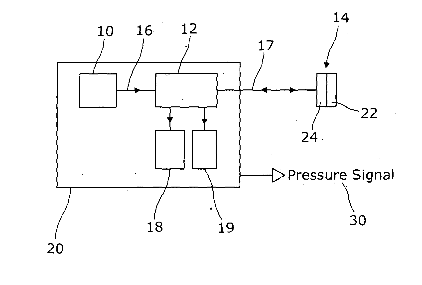
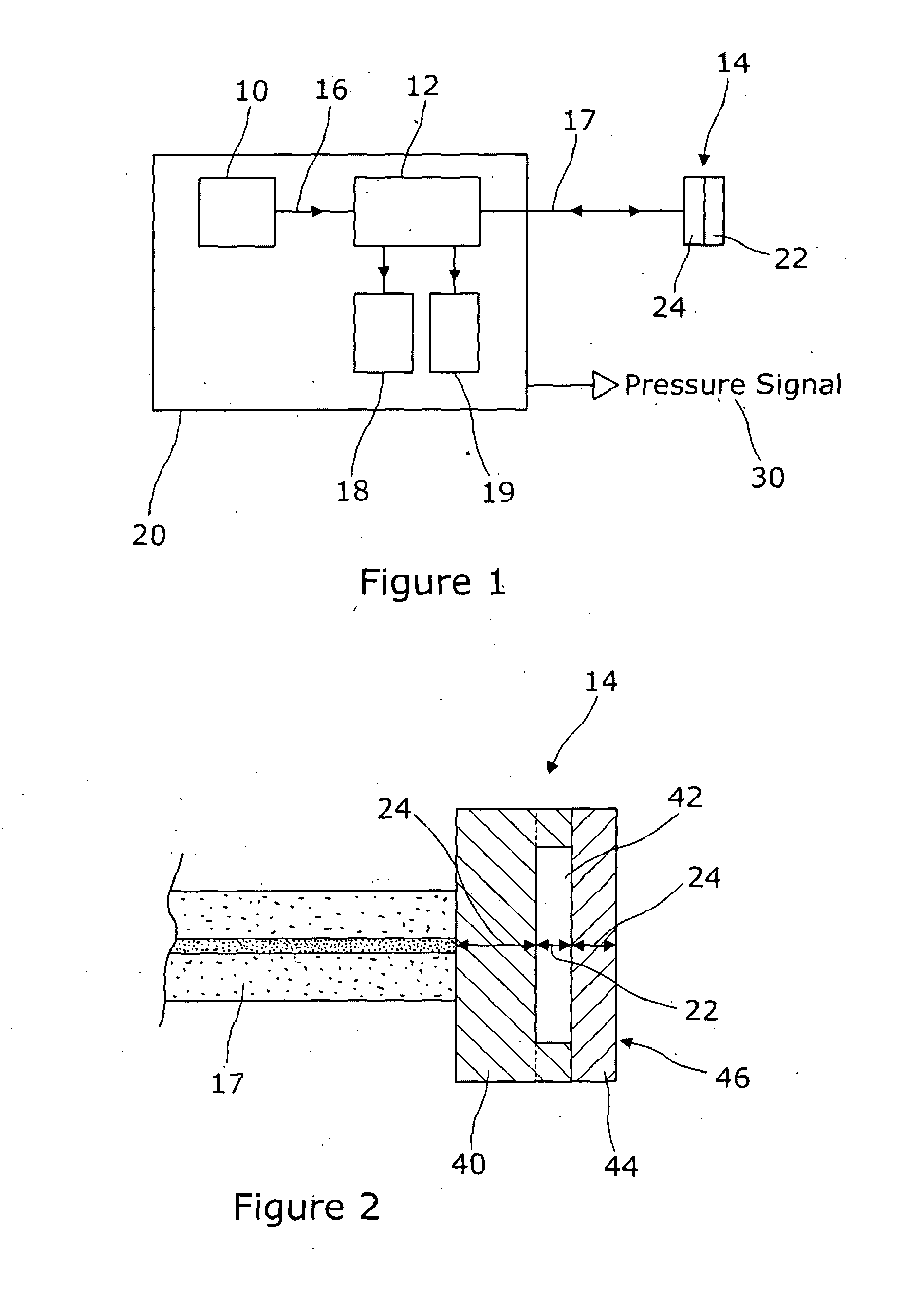
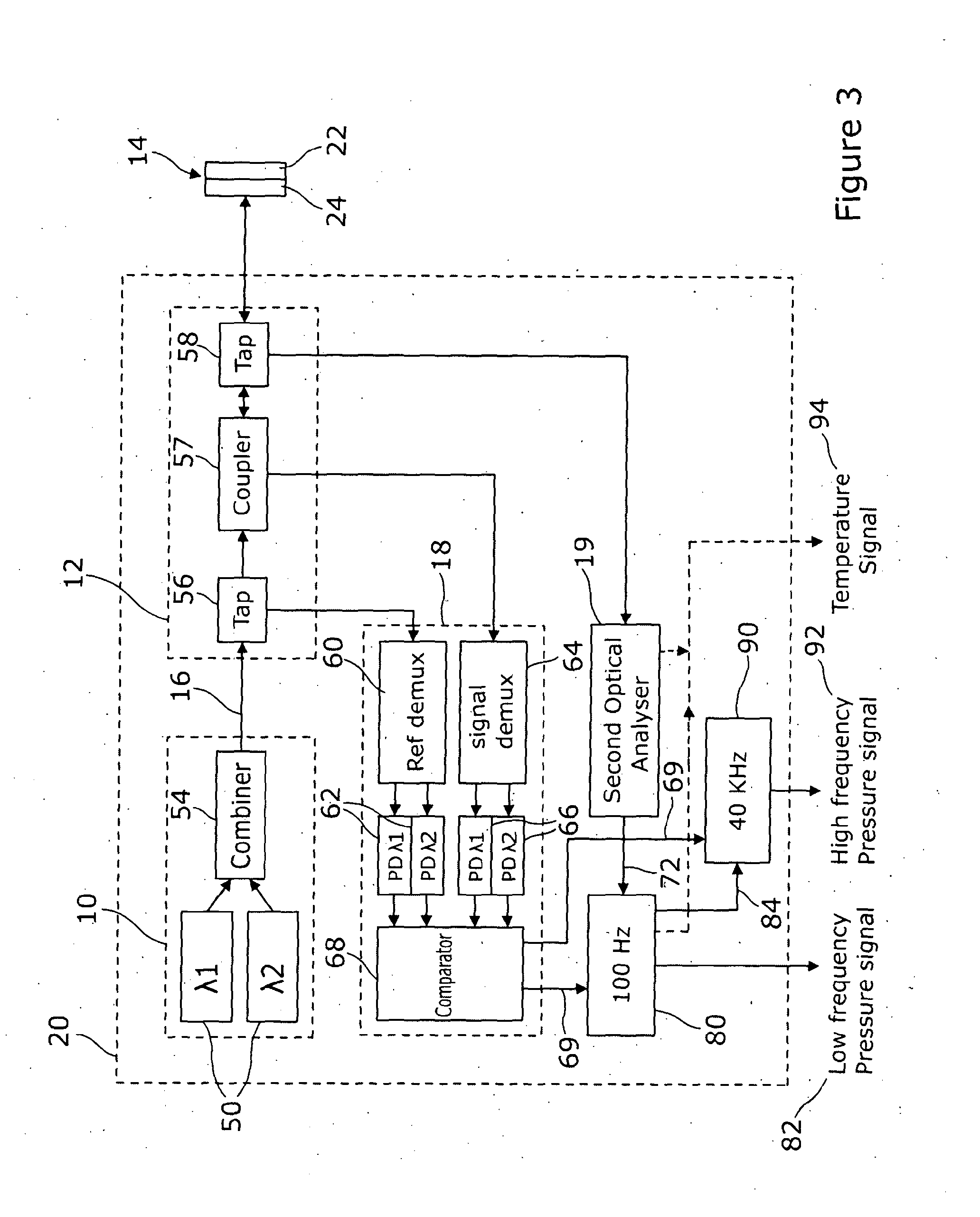
[0039]Referring to FIG. 1 there is shown schematically an optical pressure sensor embodying the invention. A light source 10 delivers probe light through an optical coupling arrangement 12 to a sensor head 14 through optical fibres 16,17. Probe light reflected back from the sensor head 14 is coupled by the coupling arrangement 12 to one or more optical analysers 18, 19 which form a part of interrogator 20. As shown in the figure, the light source 10 and the coupling arrangement 12 may also form a part of the interrogator 20. The light source 10 may comprise, for example, one or more super luminescent diodes. Broadband probe light could also or instead be provided using one or more scanning wavelength laser sources, in association with other suitable changes to the interrogator 20.

[0040]The sensor head 14 is provided with at least a pressure sensing optical cavity 22 and at least one further optical cavity which is a temperature sensing optical cavity 24. The pressure sensing and tem...


PUM

PropertyMeasurementUnit
static pressureaaaaaaaaaa
temperaturesaaaaaaaaaa
thicknessaaaaaaaaaa

Abstract

An optical pressure sensor is disclosed having a pressure sensing optical cavity. A temperature sensing optical cavity at the sensor head is used by an interrogator to correct a pressure signal for effects of temperature. The optical cavities may be, for example, Fabry Perot cavities in the sensor head.

Description

[0001]The present invention relates to an optical pressure sensor, for example an optical pressure sensor in which pressure is measured using a pressure sensing optical cavity at a sensor head, which is interrogated optically.INTRODUCTION[0002]Optical pressure sensors implemented using one or more optical cavities, such as Fabry Perot cavities are known, for example from GB 2202936, in which the interrogation of a two mirror Fabry-Perot pressure sensor head is realized using light of two different wavelengths delivered along an optical fibre. The ratios of the detected intensities of the two wavelengths in the back reflected light, suitably normalized using a reference feed directly from the light source, is used as a measure of optical path difference in the sensor head, which is in turn responsive to the applied pressure.[0003]Other optical pressure sensors based on Fabry-Perot cavities in a sensor head are described in WO2005 / 098385 and WO2009 / 077727. These documents describe sen...

Claims


Application Information

Patent Timeline
Patent Type & Authority Applications(United States)
IPC IPC(8): G01L11/02
CPCG01L11/02G01L9/0092G01L9/0079G01L27/002G01L19/04G01L19/0092G01J3/0286G01J2009/0257G01D3/028G01J3/26
Inventor PECHSTEDT, RALF-DIETERMAILLAUD, FABRICE F.M.
Owner OXSENSIS
Why Eureka
Try Eureka