
Counterweighted pump jack with reversible motors

a counterweighted, motorized technology, applied in the direction of positive displacement liquid engine, fluid removal, borehole/well accessories, etc., can solve the problems of large, heavy, expensive construction, and large walking beam style of pumping unit, and achieve the effect of suitable strength and reliability, and reliably carrying large tensile loads

Inactive Publication Date: 2015-01-22
DC INNOVATION
View PDF6 Cites 7 Cited by
  • Summary
  • Abstract
  • Description
  • Claims
  • Application Information

AI Technical Summary

Benefits of technology

This patent describes a pumping unit that uses multiple flexible connectors and drive motors to provide a safe and reliable system for lifting and supporting heavy loads. The flexible connectors are designed to ensure that the pump rod string cannot fall even if one of the connectors breaks. The power system includes hydraulic pumps, motors, and a reservoir located on the ground, with hydraulic fluid lines routed between them, which makes maintenance easier. The flexible drive elements serve as both the drive means and the load-carrying means, in contrast to previous counterweighted pump units which use separate flexible drive elements and load-carrying elements. The safety cage and other safety features enhance safety during maintenance or other activities. The technical effects of this patent include improved safety, reliability, and efficiency of the pumping unit.

Problems solved by technology

The walking beam style of pumping unit is large, heavy, and expensive to build.
If the single cable connecting the free end of the walking beam to the polished rod at the upper end of the pump rod string should break, the pump rod string will fall uncontrollably, damaging the well head and possibly losing the entire rod string into the well hole, entailing costly repairs and creating a safety hazard.
The Rotaflex® unit thus provides the benefits of counterweighting in conjunction with a unidirectionally-rotating electric primary drive motor, but has the drawback of requiring complex mechanical apparatus in order to provide the necessary lifting capacity on both the upstroke and downstroke of the downhole pump being actuated by the unit.
However, it too has disadvantageous mechanical complexities, including the requirement for the large drum associated with the traction cables, the “highly desirable” load cables in addition to the traction cables, and the large sheaves also required for the traction cables and load cables.
It is stated in the Zens patent that the size of the sheaves can be reduced by using additional cables; however, providing additional traction cables and load cables introduces additional complexity.
A further drawback of the Zens apparatus is the inherent problem of fleet angles developing with respect to the traction cables, which is addressed by introducing further mechanical complexity in the form of a mechanism for constantly tilting the axis of the drum to keep the fleet angle equal to essentially zero.

Method used


Image

  • Counterweighted pump jack with reversible motors
  • Counterweighted pump jack with reversible motors
  • Counterweighted pump jack with reversible motors

Examples


Embodiment Construction

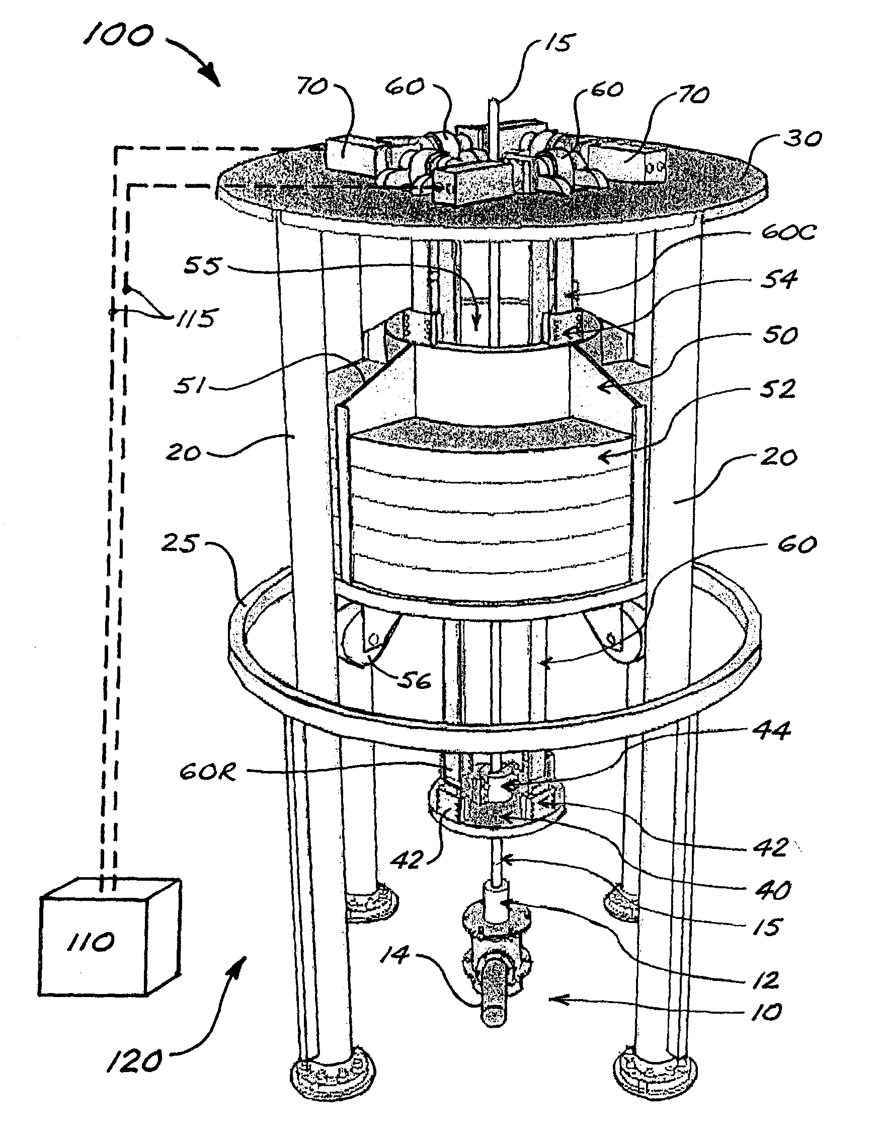
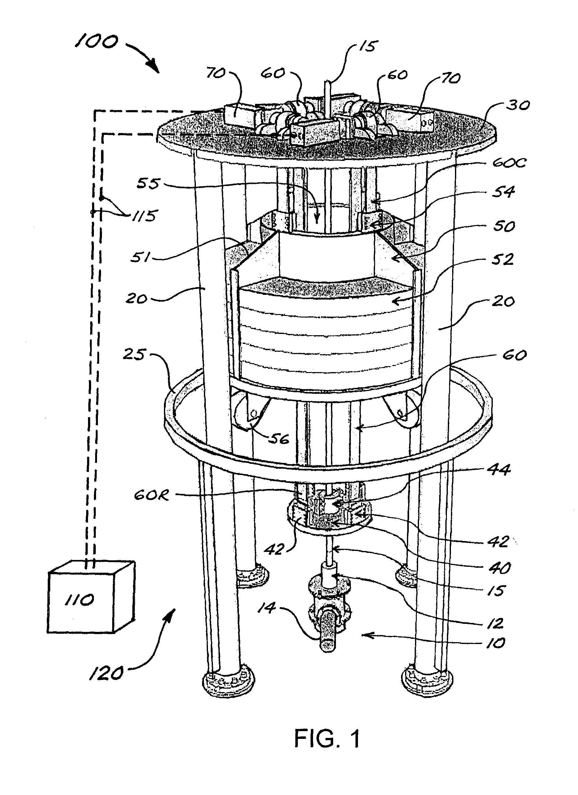
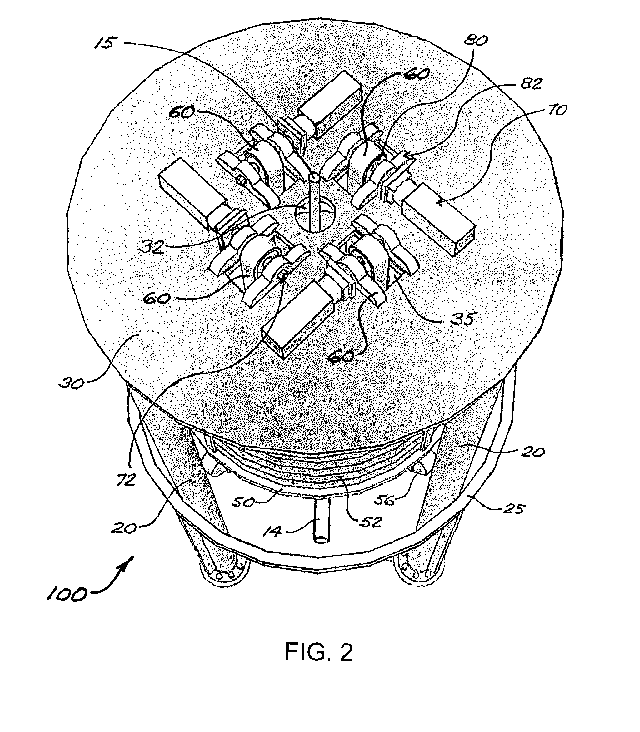
[0039]FIGS. 1-3 illustrate a first embodiment 100 of a well pumping unit in accordance with the present disclosure. Pumping unit 100 comprises a support structure 120 that may be positioned over a wellhead 10 associated with a wellbore. Wellhead 10 will typically include a stuffing box 12 through which and upward from which extends a polished rod 15 associated with a pump rod string connected to a downhole pump (not shown) disposed within a production tubing string installed in the wellbore. Wellhead 10 also includes a flow tee 14 for drawing off fluids produced from the well.

[0040]In FIGS. 1-3, support structure 120 is shown as comprising a plurality of vertical columns 20, with a perimeter support member 25 connecting columns 20 at about mid-height. This depiction is solely for conceptual illustrative purposes; the configuration of support structure 120 for a given application will be a matter of design choice, and embodiments of well pumping units in accordance with the present d...


PUM


Abstract

A counterweighted well pumping unit comprises two or more reversible motors, each of which is directly and operatively connected to a rotatable drive component mounted on a support structure positioned over a wellhead. For each motor, an elongate, flexible drive element is trained over the associated rotatable drive component, with one end of the flexible drive element connected to a counterweight assembly and the other end connected to a pump rod string associated with the wellhead. Actuation of the motors rotates the rotatable drive components, thus causing the drive elements to move the pump rod string and the counterweight assembly in opposite vertical directions. The rotational direction of the drive motors is alternated so as to alternate the directions of vertical movement of the pump rod string and the counterweight. The counterweight assembly may be concentric with or offset from the wellhead.

Description

FIELD OF THE DISCLOSURE[0001]The present disclosure relates to well pumping units for operating rod-actuated downhole oil well pumps and the like.BACKGROUND[0002]In common methods for producing fluids from a well drilled into a petroleum-bearing subsurface formation, a string of steel production tubing is positioned in the wellbore and extends from the subsurface production zone up to a wellhead at the surface. A downhole pump is disposed within the production tubing in the production zone to raise well fluids (e.g., oil, gas, formation water) to the surface, by reciprocating vertical movement of a travelling valve incorporated into the pump. The travelling valve is reciprocated by a pump rod string (or “sucker rod” string) extending upward within the production tubing to the wellhead where it connects to a “polished rod” extending upward through a wellhead tee and stuffing box to connect to a pumping unit. This type of pump is commonly referred to as a positive-displacement pump or...

Claims


Application Information

Patent Timeline
IPC IPC(8): F04B47/02E21B43/12F04B47/14
CPCF04B47/022E21B43/126F04B47/14F04B47/02
Inventor CHAIKA, DARIN, J.
Owner DC INNOVATION
Learn More