

LED bulb emitting light ray in a downward direction and manufacturing method thereof
- Summary
- Abstract
- Description
- Claims
- Application Information
AI Technical Summary
Benefits of technology
Problems solved by technology
Method used
Image

Examples
Embodiment Construction
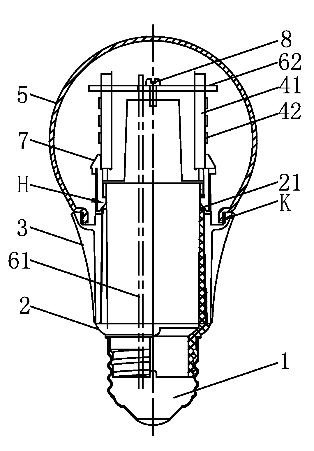
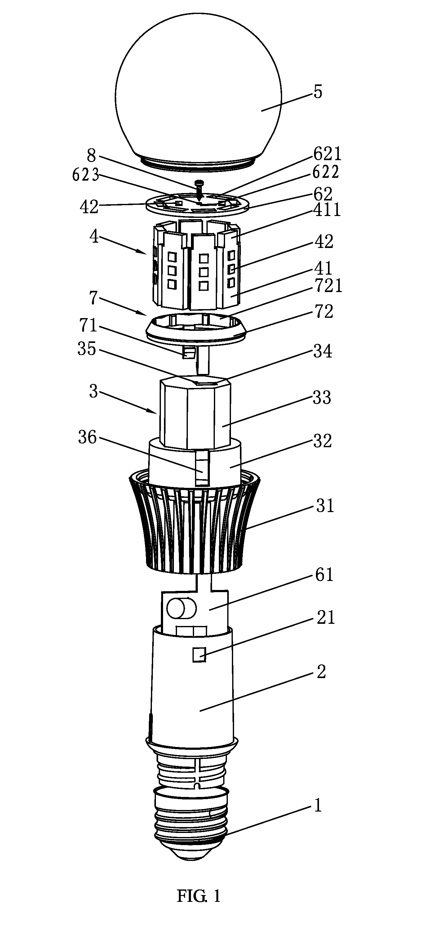
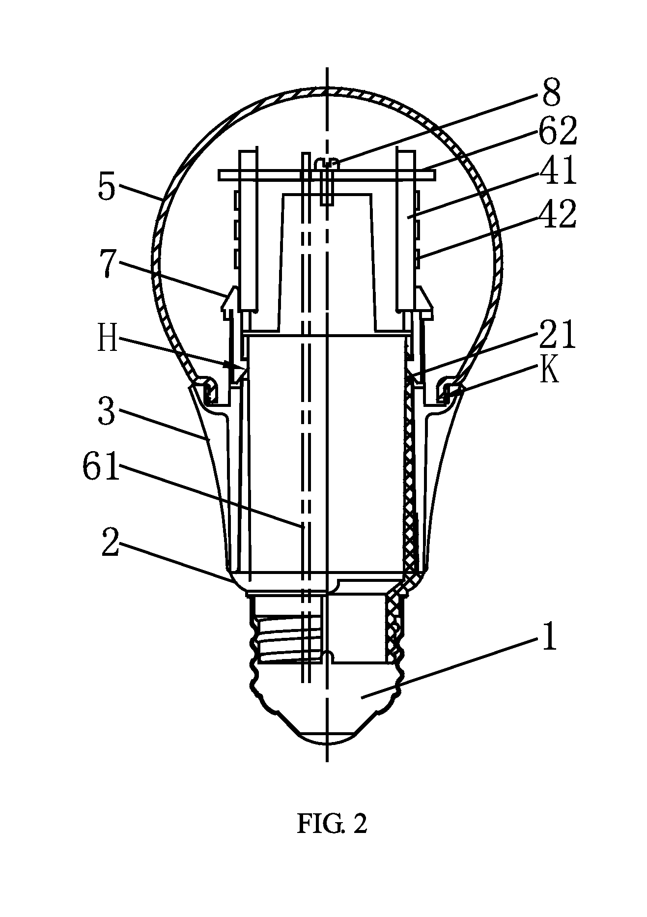
[0027]Various preferred embodiments will now be described with reference to the figures. As shown in FIG. 1, the LED bulb emitting light ray in a downward direction comprises a screw head 1, a base 2 connected to the screw head 1 by screwing, a PCB board 61 longitudinally arranged within the base 2 and connected with the PCB board 62 on the top of the lamp body by tin soldering, a lamp body 3 mounted on the base 2, and the bottom of the LED aluminum substrate component 4 longitudinally arranged at the PCB board 62 on the top of the lamp body 3 and covering the lamp body 3 is fixed by a base buckle 7, the LED aluminum substrate component 4 is fixed to the lamp body 3 by fastening the hook buckle 71 convexly arranged on the bottom of the base buckle 7 to a buckle hole 21 of the base (referring to H shown in FIG. 2), the top of the LED aluminum substrate component 4 is connected with the PCB board 62 on the top of the lamp body by tin soldering, the PCB board 62 on the top of the lamp ...
PUM
 Abstract
Description
Claims
Application Information