Eureka AIR delivers breakthrough ideas for toughest innovation challenges, trusted by R&D personnel around the world.

Backlight module and corresponding liquid crystal display device

Active Publication Date: 2015-01-22
TCL CHINA STAR OPTOELECTRONICS TECH CO LTD
View PDF3 Cites 0 Cited by
  • Summary
  • Abstract
  • Description
  • Claims
  • Application Information

AI Technical Summary

Benefits of technology

The present invention provides a solution for the problem of oversized thickness of conventional backlight modules and their corresponding liquid crystal display devices. The invention reduces the thickness of the backlight module without affecting the optical quality of the emitted lights or increasing manufacturing costs. The LEDs in the backlight module have a first lens for enhancing their light-emitting efficiency. The technical effects of the invention include a thinner and flatter backlight module, improved light-emitting quality, and reduced manufacturing costs.

Problems solved by technology

1. Directly reduce the light-mixing distance D from the light-emitting surface of the light sources 12 to the diffuser panel 13; however this solution will decrease the uniformity of the lights emitted from the backlight module; and
2. Increase the number of the light sources in the backlight module; this solution can relatively reduce the light-mixing distance D from the light-emitting surface of the light sources 12 to the diffuser panel 13 without affecting the uniformity of the lights emitted from the backlight module, but causes an increase in the manufacturing cost of the backlight module.

Method used


Image

  • Backlight module and corresponding liquid crystal display device
  • Backlight module and corresponding liquid crystal display device
  • Backlight module and corresponding liquid crystal display device

Examples


Embodiment Construction

[0042]Following description of each embodiment is referring to the accompanying drawings so as to illustrate practicable specific embodiments in accordance with the present invention. The directional terms described in the present invention, such as upper, lower, front, rear, left, right, inner, outer, side and etc., are only directions referring to the accompanying drawings, so that the used directional terms are used to describe and understand the present invention, but the present invention is not limited thereto.

[0043]In the drawings, units with similar structure are labeled with the same reference number.

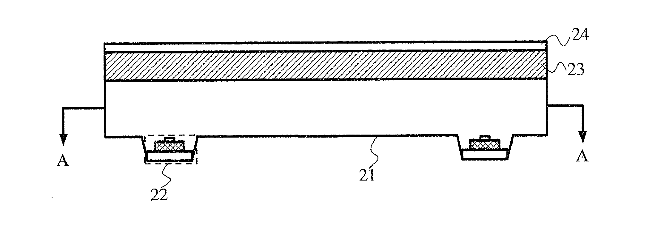
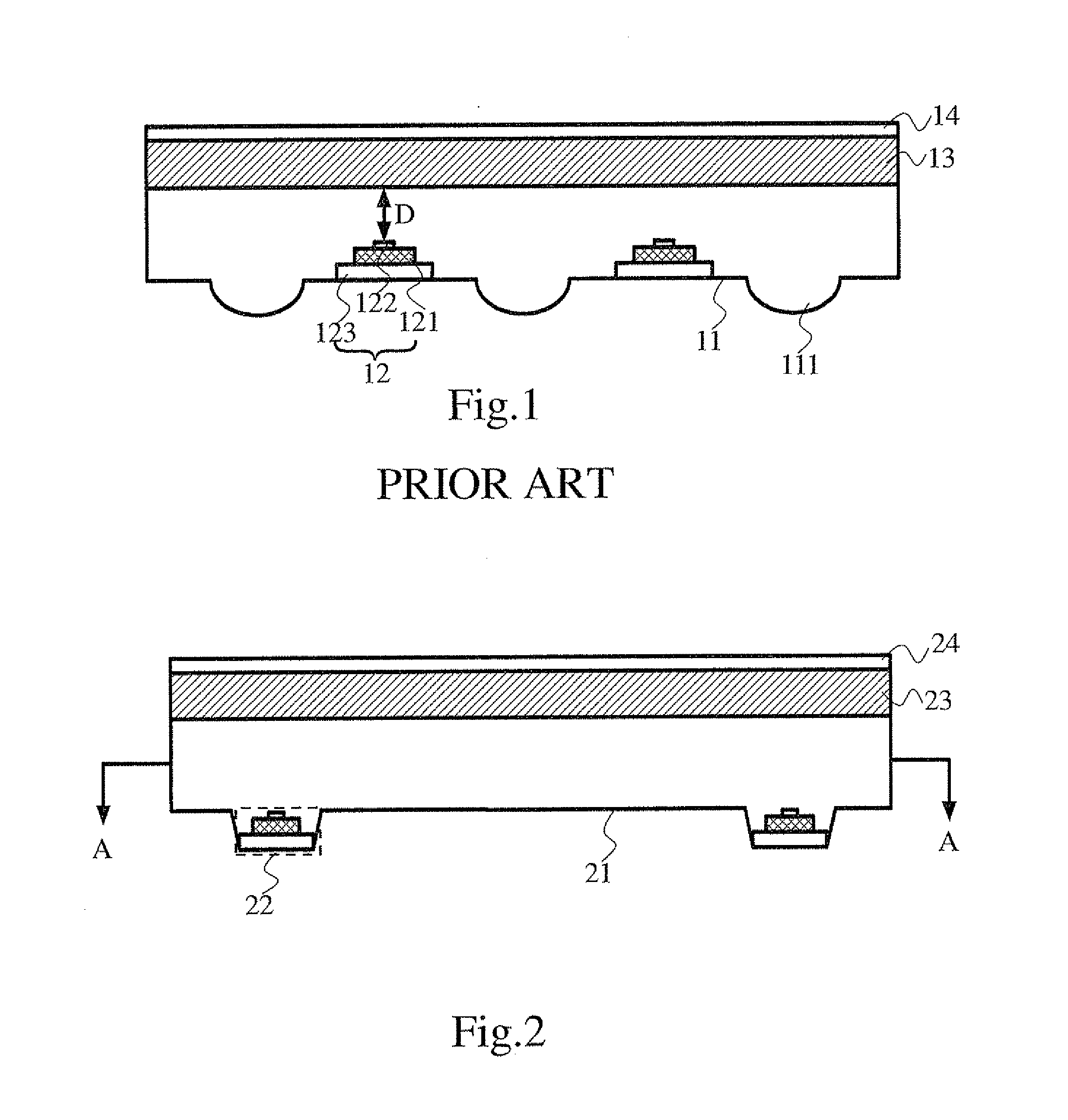
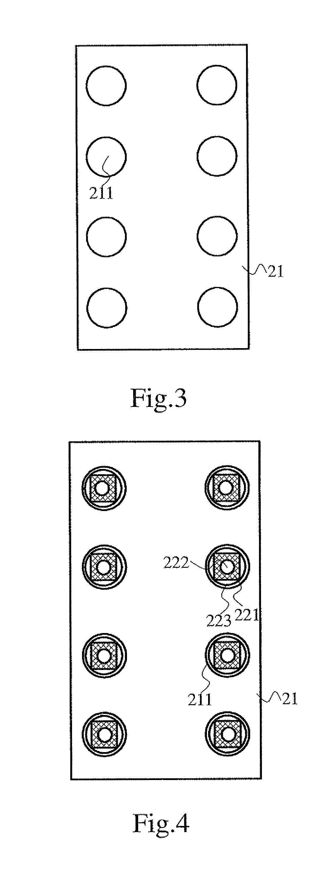
[0044]Please refer to FIGS. 2, 3 and 4, wherein FIG. 2 is a side view of a first embodiment of a backlight module in accordance with the present invention; FIG. 3 is a top view taken in the direction line A-A in FIG. 2, showing the first embodiment of the backlight module of the present invention without light sources; FIG. 4 is a top view taken in the direction line A-A in FIG...


PUM


Abstract

The present invention relates to a backlight module and a corresponding liquid crystal display panel. The backlight module includes a backboard having multiple concave portions formed on an inner surface of the backboard and multiple light sources mounted in the concave portions. The backlight module and the corresponding liquid crystal display device of the present invention can reduce the thickness of direct-type backlight module without affecting the optical quality of the lights emitted from the backlight module and increasing the manufacturing cost of the backlight module.

Description

BACKGROUND OF THE INVENTION[0001]1. Field of the Invention[0002]The present invention relates to a field of liquid crystal display technology, especially to a backlight module and a corresponding liquid crystal display device that the thickness of the direct-type backlight module is reduced.[0003]2. Description of the Related Art[0004]Liquid crystal display devices have been widely used in many kinds of electronic products. Liquid crystal display devices are mostly backlight-type liquid crystal devices that have a liquid crystal panel and a backlight module. Backlight modules are sorted into side-light type and direct-light type based on the incident position of their light sources.[0005]FIG. 1 is a schematic view of a conventional direct-light type backlight module. The direct-light type backlight module includes a backboard 11, multiple light sources 12, a diffuser panel 13 and an optical film 14. The light sources 12 are mounted on the backboard 11. The diffuser panel 13 has a li...

Claims


Application Information

Patent Timeline
IPC IPC(8): G02F1/1335
CPCG02F1/133608G02F1/133603G02F2001/133607G02F2001/133628G02F1/133606F21Y2115/10F21Y2107/00F21Y2107/10G02F1/133628G02F1/133607
Inventor HUANG, JIANFACAO, QIANHU, CHECHANG
Owner TCL CHINA STAR OPTOELECTRONICS TECH CO LTD
Why Eureka
Eureka Blog
Learn More