Rotation drive device

a technology of rotating drive and rotating shaft, which is applied in the direction of casing/cabinet/drawer details, instruments, casings/cabinets/drawers, etc., can solve the problems of reducing the efficiency of cooling efficiency, the influence of such deformation of the partition wall of the housing, and the inability to take into account the influence of such deformation, so as to improve the reliability of operation against external pressure, the first and second partition walls can be further improved, and the deformation

Inactive Publication Date: 2015-01-22
SONY CORP
View PDF5 Cites 7 Cited by
  • Summary
  • Abstract
  • Description
  • Claims
  • Application Information

AI Technical Summary

Benefits of technology

[0007]According to the present disclosure, the opposite ends of the shaft member inserted in the rotating object are fixedly joined to the inner surfaces of the first and second partition walls located on the opposite sides in the first direction of the rotating object, on the opposite sides in the first direction in which the shaft member is extended. Therefore, the shaft member has the function of supporting the rotating object for rotation and supporting the first and second partition walls from the inside. Therefore, the rigidity of the first and second partition walls against external pressure exerted from the first direction is improved, and therefore, the deformation of the first and second partition walls due to the external pressure is reduced or prevented. Therefore, the normal operation of the rotation drive device is maintained even when external pressure is exerted thereon.
[0008]As described above, according to the present disclosure, the reliability of operation against external pressure can be further improved.

Problems solved by technology

Therefore, if pressure is externally exerted on the housing, the partition wall of the housing is likely to be deformed, resulting in an influence on the internal configuration.
However, in the technology described in JP 2007-122132A, the influence of such deformation of the partition wall of the housing is not sufficiently taken into consideration.
Therefore, in the technology described in JP 2007-122132A, when external pressure is exerted on the housing, the rotation drive device for thermal dissipation is likely to fail to smoothly operate due to the deformed partition wall, leading to a decrease in the efficiency of thermal dissipation (cooling efficiency).

Method used


Image

  • Rotation drive device
  • Rotation drive device
  • Rotation drive device

Examples


Embodiment Construction

)

[0015]Hereinafter, preferred embodiments of the present disclosure will be described in detail with reference to the appended drawings. Note that, in this specification and the appended drawings, structural elements that have substantially the same function and structure are denoted with the same reference numerals, and repeated explanation of these structural elements is omitted.

[0016]Note that the description will be given in the following order.

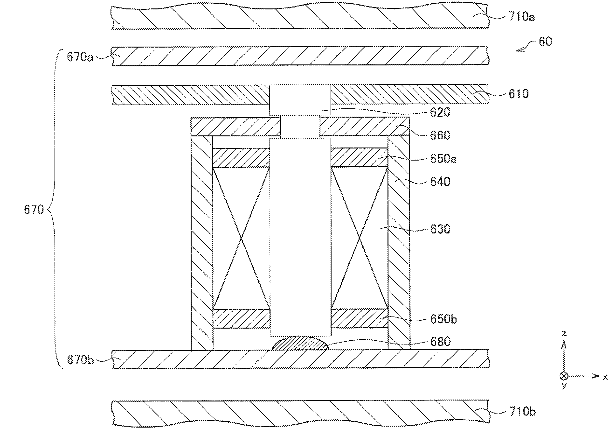
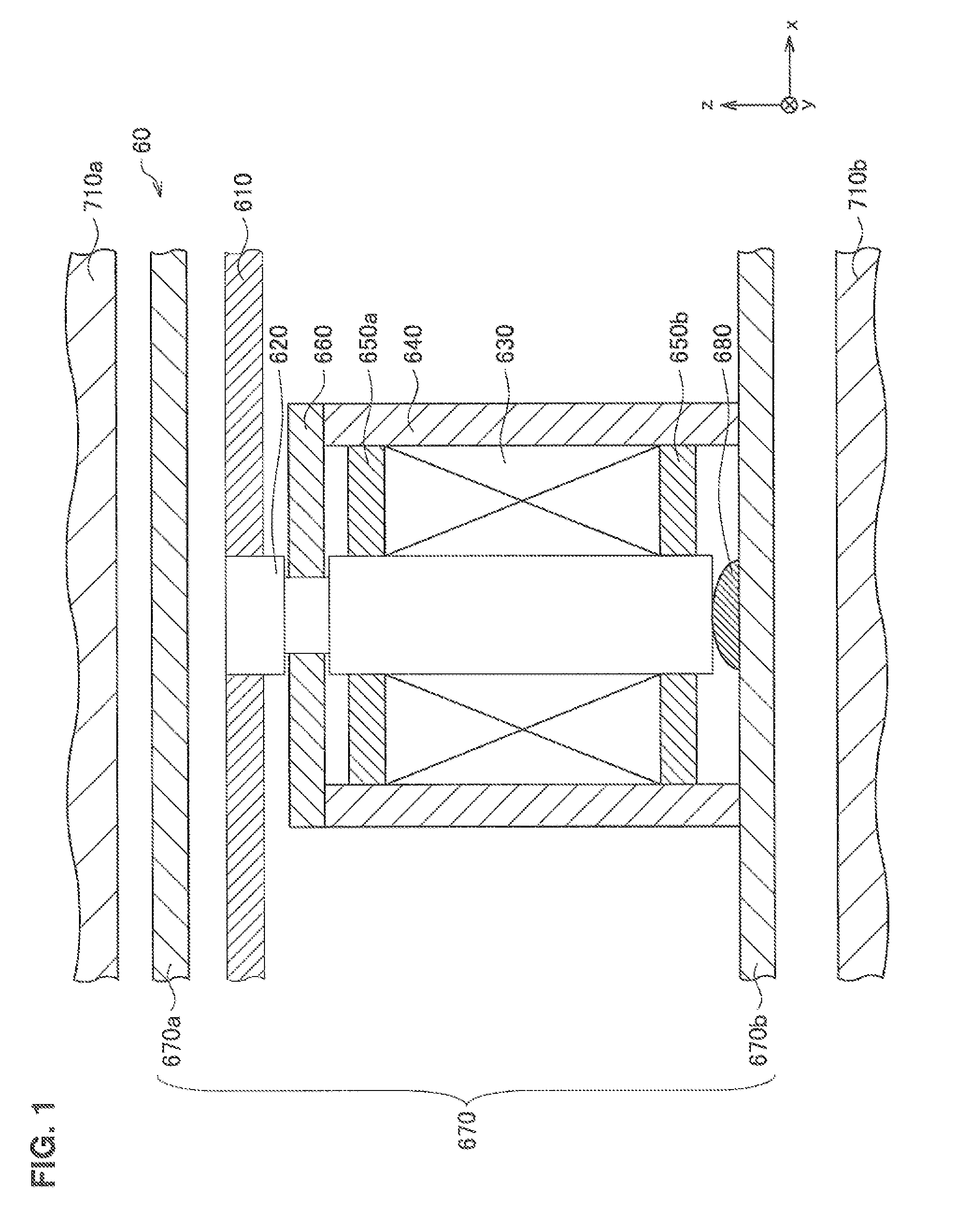
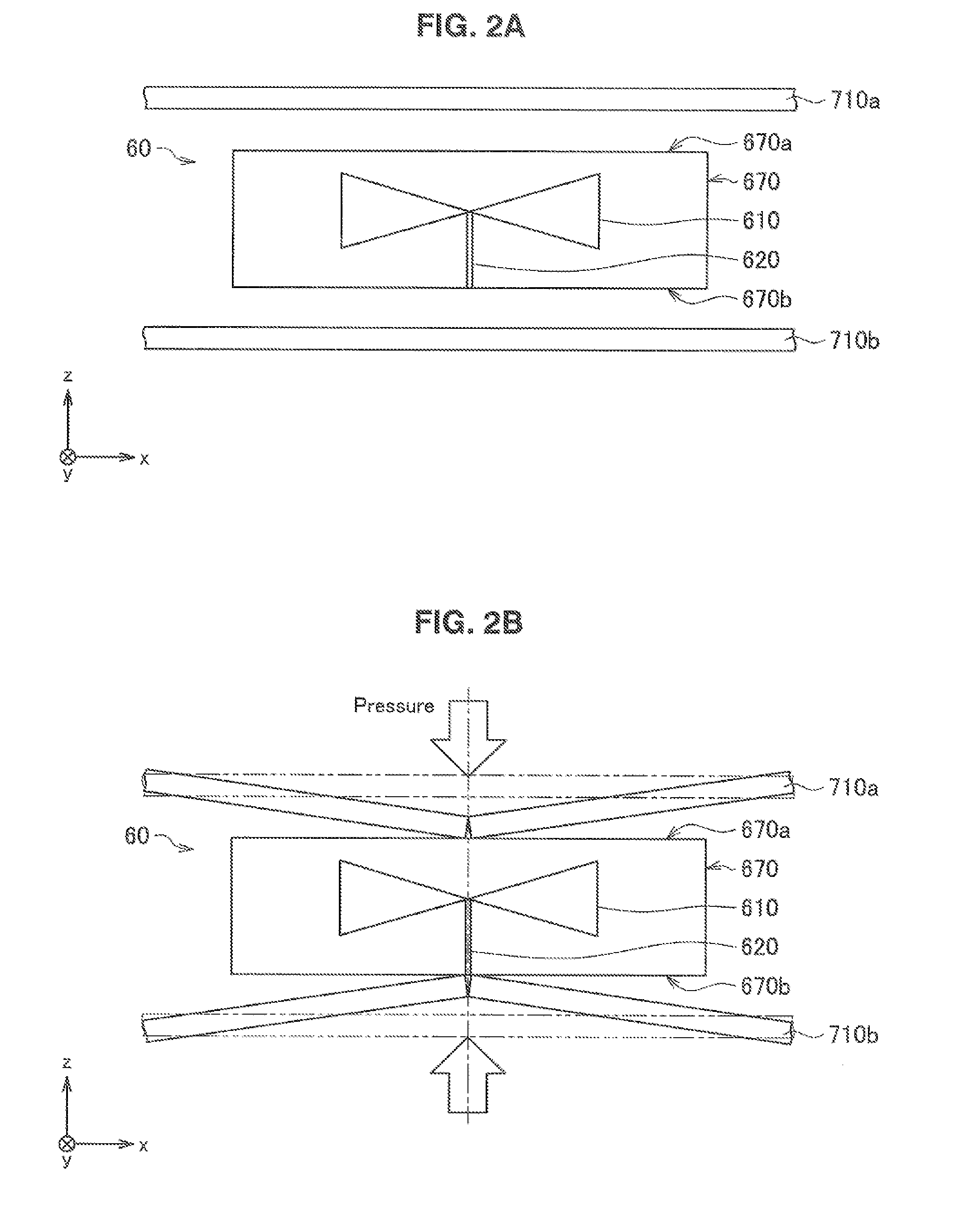
[0017]1. Commonly Used Existing Cooling Fan[0018]1-1. Configuration of Commonly Used Existing Cooling Fan[0019]1-2. Study of Commonly Used Existing Cooling Fan

[0020]2. Cooling Fan of This Embodiment[0021]2-1. Configuration of Cooling Fan of This Embodiment[0022]2-2. Advantages of Cooling Fan of This Embodiment

[0023]3. Summary

[0024]Firstly, in order to clearly describe the present disclosure, how the present inventors have discovered the present disclosure will be described in detail. In the description that follows, a commonly used coolin...


PUM


Abstract

Provided is a rotation drive device including a shaft member extending in a first direction, and a rotating object configured to allow the shaft member to be inserted in the rotating object, and configured to rotate around an axis of rotation extending in the first direction relative to the shaft member. Opposite ends of the shaft member are fixedly joined to respective inner surfaces of a first partition wall and a second partition wall located on the opposite sides in the first direction of the rotating object.

Description

CROSS REFERENCE TO RELATED APPLICATIONS[0001]This application claims the benefit of Japanese Priority Patent Application JP 2013-151432 filed Jul. 22, 2013, the entire contents of which are incorporated herein by reference.BACKGROUND[0002]The present disclosure relates to rotation drive devices.[0003]In the field of portable electronic apparatuses such as laptop or notebook personal computers (PCs) etc., there has in recent years been a demand for a technology for efficiently dissipating heat generated in the apparatus to the outside because of the increasing integration degree and speed of integrated circuits such as a central processing unit (CPU) etc. provided in the apparatus. For example, JP 2007-122132A discloses a portable electronic apparatus in which a space for thermal insulation is provided between a heat source, such as a CPU etc., and a battery, and a rotation drive device, such as a cooling fan, which is driven to rotate, thereby causing air to flow, is used to draw ai...

Claims


Application Information

Patent Timeline
Patent Type & Authority Applications(United States)
IPC IPC(8): H05K5/02F04D29/053H05K7/20
CPCF04D29/053H05K7/20136H05K5/0217F04D25/062G06F1/203
Inventor KOIZUMI, AKIHIKO
Owner SONY CORP
Why Eureka
Try Eureka