Piezoelectric fan

a technology of piezoelectric elements and fans, applied in the direction of machines/engines, positive displacement liquid engines, machine/engine details, etc., can solve the problems of disturbance of drive signals for driving piezoelectric elements, inability to obtain desired vibration, and possible electrical conduction. , to achieve the effect of reliably obtaining desired vibration and preventing electrical conduction

Inactive Publication Date: 2015-01-22
MURATA MFG CO LTD
View PDF6 Cites 9 Cited by
  • Summary
  • Abstract
  • Description
  • Claims
  • Application Information

AI Technical Summary

Benefits of technology

[0015]Preferred embodiments of the present invention provide a piezoelectric fan that prevents electrical conduction between a vibrating plate and an external housing, and reliably obtains desired vibration.
[0017]In this configuration, a main-body fixing hole of the main-body fixing portion is located in an area where the vibrating plate is not in contact with a supporting body. Therefore, even when the piezoelectric fan is secured to an external housing with conductive screws, the vibrating plate and the external housing are not electrically conducted to each other. It is thus possible to prevent external noise from propagating to the vibrating plate.
[0020]With this configuration, it is possible to provide a compact piezoelectric fan while providing the operation and effect described above. In particular, when the main-body fixing portion is positioned to the blade side compared with the supporting portion, it is possible to further reduce the size of the piezoelectric fan.
[0024]With this configuration, where the holding member is electrically insulated from the outside, it is possible to prevent noise from being superimposed on drive signals through the holding member.

Problems solved by technology

As a result, noise may propagate through the external housing to the vibrating plate 11.
If noise propagates to the vibrating plate 11, drive signals for driving the piezoelectric elements are disturbed by the noise and desired vibration cannot be obtained.

Method used


Image

  • Piezoelectric fan
  • Piezoelectric fan
  • Piezoelectric fan

Examples


Embodiment Construction

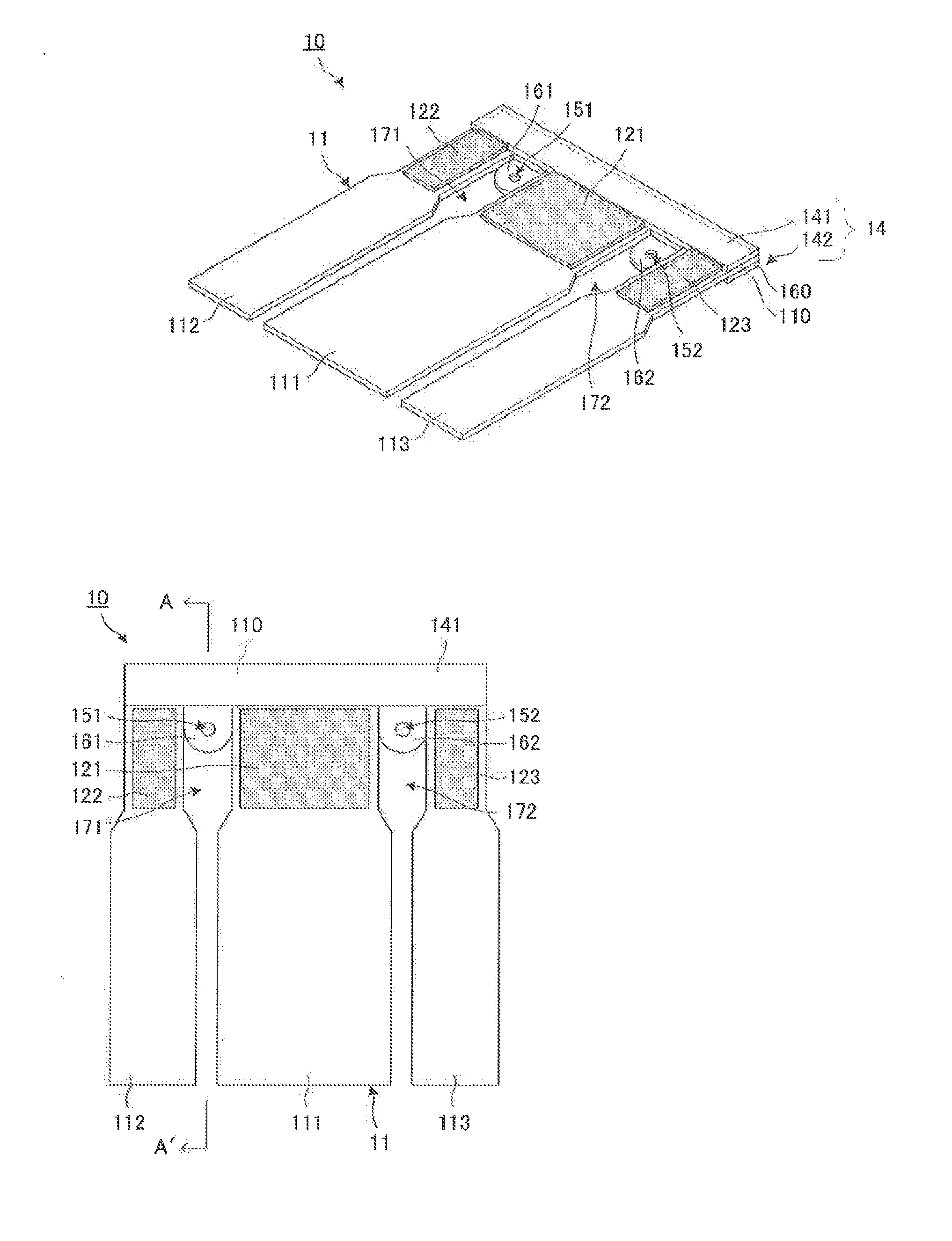
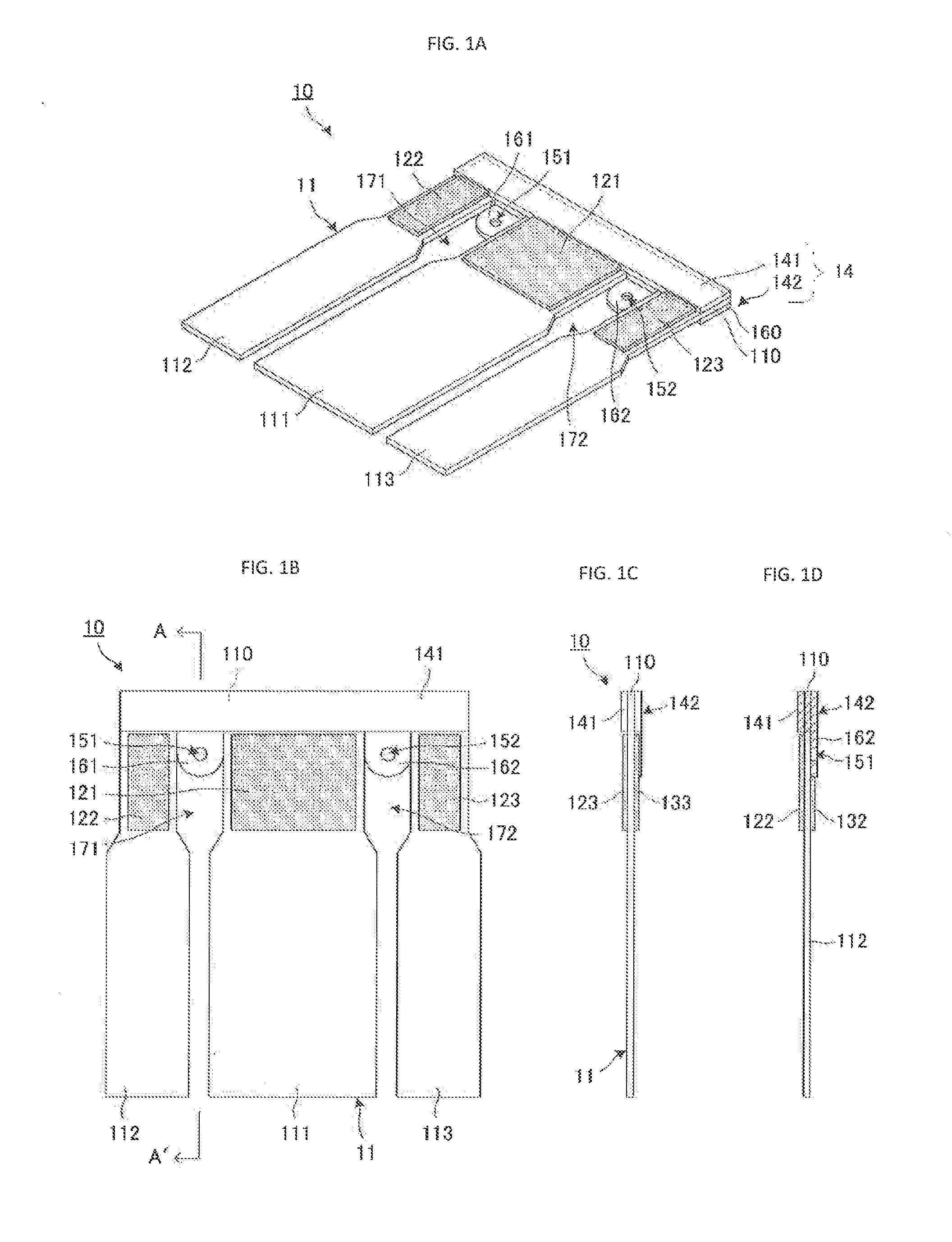
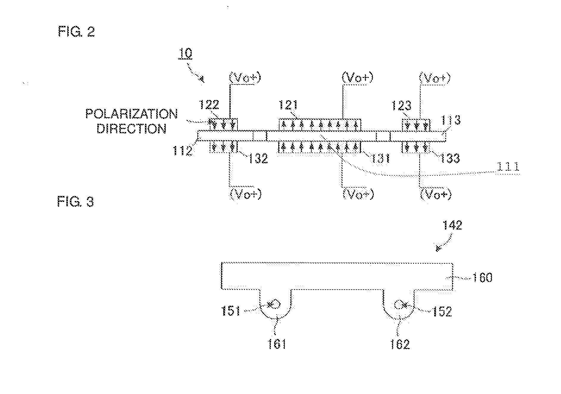
[0033]A piezoelectric fan according to a first preferred embodiment of the present invention will be described with reference to the drawings. FIG. 1A is an external perspective view of a piezoelectric fan 10 according to the first preferred embodiment of the present invention. FIG. 1B is a plan view of the piezoelectric fan 10 according to the first preferred embodiment of the present invention. FIG. 1C is a lateral view of the piezoelectric fan 10 according to the first preferred embodiment of the present invention. FIG. 1D is a cross-sectional view taken along line A-A′ of the piezoelectric fan 10 according to the first preferred embodiment of the present invention. FIG. 2 illustrates a driving concept of the piezoelectric fan 10 according to the first preferred embodiment of the present invention. FIG. 3 is a plan view of a holding member 142 according to the first preferred embodiment of the present invention.

[0034]The piezoelectric fan 10 includes a vibrating plate 11, piezoel...


PUM


Abstract

A piezoelectric fan in which vibration of blades is unaffected by external noise includes a vibrating plate including blades and a base. First piezoelectric elements are attached to a side of a first blade adjacent to the base. Second piezoelectric elements are attached to a side of a second blade adjacent to the base. Third piezoelectric elements are attached to a side of a third blade adjacent to the base. A holder includes a supporting body and a holding member that sandwich the base therebetween. The holding member has a supporting portion and main-body fixing portions including respective main-body fixing holes. The main-body fixing portions extend from the supporting portion.

Description

BACKGROUND OF THE INVENTION[0001]1. Field of the Invention[0002]The present invention relates to a piezoelectric fan that blows air by using a piezoelectric element as a drive source to a vibrate blade.[0003]2. Description of the Related Art[0004]Conventional piezoelectric fans that use a piezoelectric element as a drive source are described, for example, in Japanese Unexamined Patent Application Publication No. 2-33500 and International Publication No. 2009 / 119431.[0005]The piezoelectric fan described in Japanese Unexamined Patent Application Publication No. 2-33500 includes a vibrating plate and piezoelectric elements. One end of the vibrating plate is divided into three blades, whereas the other end of the vibrating plate is provided with main-body fixing holes. The piezoelectric elements are attached to the respective blades. The piezoelectric element on the central blade and the piezoelectric elements on the right and left blades are polarized in opposite directions. When an al...

Claims


Application Information

Patent Timeline
Patent Type & Authority Applications(United States)
IPC IPC(8): F04D33/00F04D25/06
CPCF04D33/00F04D25/0606F04D23/006H01L23/467H01L41/094H01L2924/0002H10N30/2042H01L2924/00
Inventor TANAKA, NOBUHIRA
Owner MURATA MFG CO LTD
Why Eureka
Try Eureka