Robot system and calibration method of the robot system

a robot system and robot technology, applied in the field of robot systems, can solve the problems of large quantization error, insufficient measurement accuracy of the camera, and insufficient use of the camera, so as to reduce the influence of a large quantization error in the optical axis direction, improve the accuracy of the calibration between the robot coordinate system and the vision coordinate system, and improve the accuracy of the calibration.

Active Publication Date: 2015-01-22
CANON KK
View PDF14 Cites 72 Cited by
  • Summary
  • Abstract
  • Description
  • Claims
  • Application Information

AI Technical Summary

Benefits of technology

[0015]According to the present invention, markers of two of at least three teaching points have the same inclination in relation to the optical axis, and the two teaching points are placed on different positions on the same plane normal to the optical axis. Therefore, the influence of a large quantization error in the opti

Problems solved by technology

However, in the method described in Japanese Patent No. 3644991, the measurement accuracy of the camera may not be sufficiently utilized depending on teaching points used in the hand-eye calibration.
In general, a measurement error of a camera is large in the optical axis direction due to influence of a quantization error.
More specifically, when a camera including light receiving units with finite pixels measures the position of an object, detected positions of the object are discrete, and there is a quantization error.
A position measurement error in the optical axis direction of the camera is composed of a position measurement error of two points in the horizontal axis direction of the ca

Method used


Image

  • Robot system and calibration method of the robot system
  • Robot system and calibration method of the robot system
  • Robot system and calibration method of the robot system

Examples


first embodiment

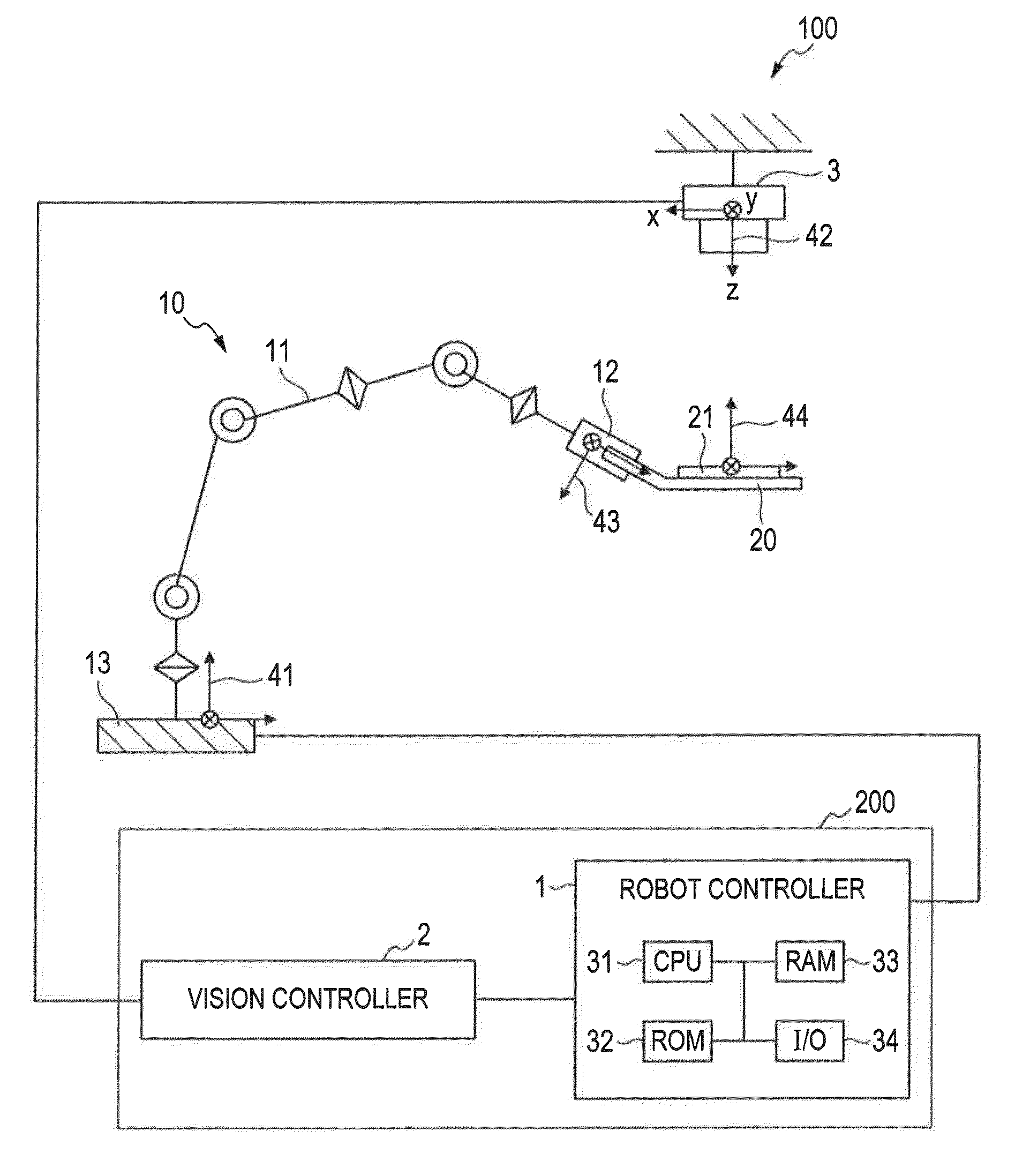
[0024]A first embodiment of the present invention will be described with reference to FIGS. 1 to 5. First, a schematic configuration of a robot system of the present embodiment will be described with reference to FIG. 1.

[0025][Robot System]

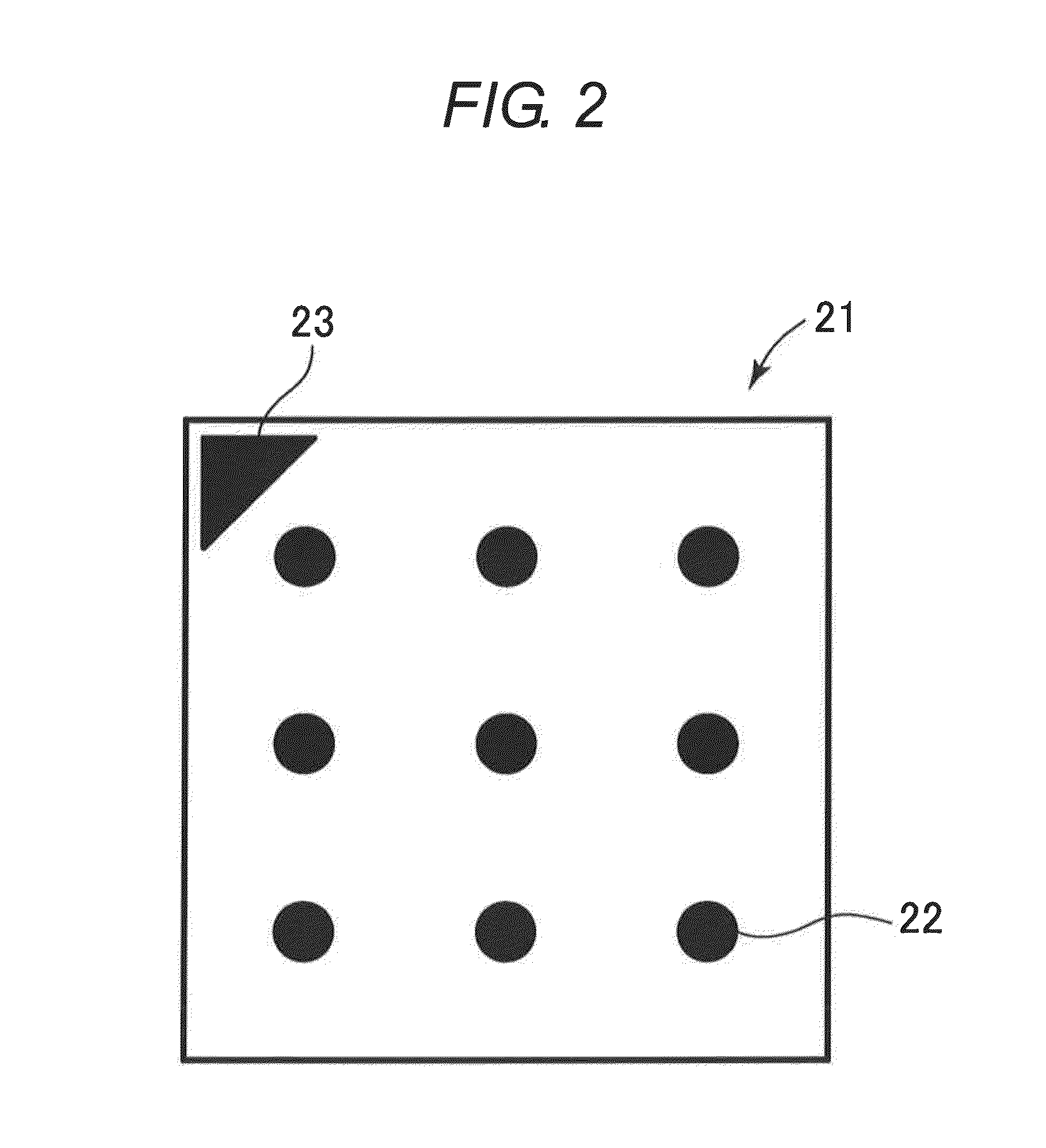
[0026]A robot system 100 of the present embodiment includes a control apparatus 200, a robot body 10, and a camera 3 as a visual sensor. The control apparatus 200 controls a position and an orientation of the robot body 10 and uses a measured value of the camera 3 to calculate the position and the orientation of a work. The control apparatus 200 includes a robot controller 1 and a vision controller 2. The robot body 10 and the vision controller 2 are connected to the robot controller 1. The camera 3 is connected to the vision controller 2. A hand 12 as an end effector of the robot body 10 holds a calibration jig 20. Hereinafter, the components will be described.

[0027]The robot body 10 includes a multi-jointed arm 11 (hereinafter, called “arm”) and...

second embodiment

[0059]A second embodiment of the present invention will be described with reference to FIG. 6. The camera 3 as a visual sensor is fixed at a position different from the robot body 10 in the description of the first embodiment. In the present embodiment, a camera 4 as a visual sensor is placed on the robot body 10. The marker 21 for calibration is fixed at a position different from the robot body 10. Other configurations are the same as in the first embodiment, and differences from the first embodiment will be mainly described.

[0060]The camera 4 is mounted on the tip of the arm 11, and the operation of the robot body 10 can position the camera 4 in an arbitrary position and orientation in the operation range of the robot body 10. The camera 4 is connected to the vision controller 2.

[0061]The vision controller 2 converts an image signal imported through the camera to a contrast signal based on grayscale and stores the contrast signal in the frame memory. The vision controller 2 also p...

third embodiment

[0069]A third embodiment of the present invention will be described with reference to FIGS. 1 to 3B. In the first embodiment, the position and orientations at three teaching points used in the calibration are based on the assumption that the robot body 10 can take the target positions and orientations on the calibration plane A. In the present embodiment, there is an obstacle (not illustrated) below the calibration plane A, and the robot body 10 cannot take at least one of the three teaching points on the plane A that are used in the calibration. The robot body may recognize the existence of the obstacle as known layout information of the robot system 100 set in advance, or the robot body may recognize the existence of the obstacle through imaging by the camera 3.

[0070]Only the setting method of three teaching points used in the calibration is different from the first embodiment. Therefore, differences from first embodiment will be mainly described.

[0071]In the setting method of thr...


PUM


Abstract

A control apparatus calculates a calibration value based on a position in the robot coordinate system 41 and a position in the vision coordinate system42, for at least three teaching points set within a calibration area. Markers 21 of two of the three teaching points have the same inclination in relation to an optical axis of a camera 3 as a visual sensor, and the two points are placed on different positions of the same plane normal to the optical axis. The remaining one of the three teaching points other than the two points is set such that the inclination of the marker 21 in relation to the optical axis is different from that of the two points. As a result, influence of a large quantization error in the optical axis direction as a measurement error of the camera 3 can be reduced.

Description

BACKGROUND OF THE INVENTION[0001]1. Field of the Invention[0002]The present invention relates to a robot system in which a visual sensor, such as a camera, measures a position of a work to correct an operating position of a robot body and to a calibration method of the robot system for calibrating the robot system.[0003]2. Description of the Related Art[0004]In recent years, automatic assembly by a robot is often used in a production line of a factory to automate operation and save manpower. In the automatic assembly, a system with a combination of a robot body, such as a multi-jointed arm, and a visual sensor, such as a camera, is used. Particularly, there is an increased need recently for a visual sensor to three-dimensionally measure a work as an object of operation.[0005]When a visual sensor measures a position of a work to correct operation of a robot body based on the position, position and orientation data of the work measured by the visual sensor needs to be converted to dat...

Claims


Application Information

Patent Timeline
IPC IPC(8): B25J9/16
CPCY10S901/47B25J9/1692G05B2219/39008G05B2219/39022
Inventor AMANO, SHINGO
Owner CANON KK
Why Eureka
Try Eureka