
Integrated multi-function window

a multi-functional window and integrated technology, applied in the field of building materials, can solve the problems of inconvenient mounting, high cost of materials, and inability to achieve the sunshade effect in one direction, so as to improve the windproof performance of outdoor sunshade curtains, reduce the cost of materials, and reduce the effect of heat radiation

Active Publication Date: 2015-01-29
NINGBO XIANFENG NEW MATERIAL
View PDF8 Cites 20 Cited by
  • Summary
  • Abstract
  • Description
  • Claims
  • Application Information

AI Technical Summary

Benefits of technology

The present invention is a window that has multiple functions, including energy saving, sun shading, heat insulation, and light penetration. The window is simple and reliable in its configuration and is good at withstanding wind. This invention eliminates the need for multiple mounting components and reduces construction time and cost.

Problems solved by technology

However, sun-shading products are mounted so separately from the windows of buildings presently in this country that materials are wasted for repeated installation even though the energy saving effect could be achieved to some extent.
Even though the components for mounting the sliding window and those for mounting the curtain cloth are combined with each other to some extent in said window frame profile, the window frame profile has a large number of parts and a complicated structure and could not be conveniently mounted.
Moreover, the position for mounting the window cover is only set on one surface of said window frame and the sun-shading effect could only be achieved in one single direction.
As such, the problem for repetitive mounting still exits in the window frame, and the materials and human resources are wasted.
In the meantime, the window frame formed by using said window frame profile still has a poor windproof property.
In conclusion, the conventional windows have such disadvantages that the outer windows are constructed by glass windows, which could permit daylight to pass through and control the flow of air into and out of rooms, but do not have the sun-shading or heat preserving function.
The existing windows have a complicated window structure and require time, labor and cost consuming double constructions.

Method used


Image

  • Integrated multi-function window
  • Integrated multi-function window
  • Integrated multi-function window

Examples


first embodiment

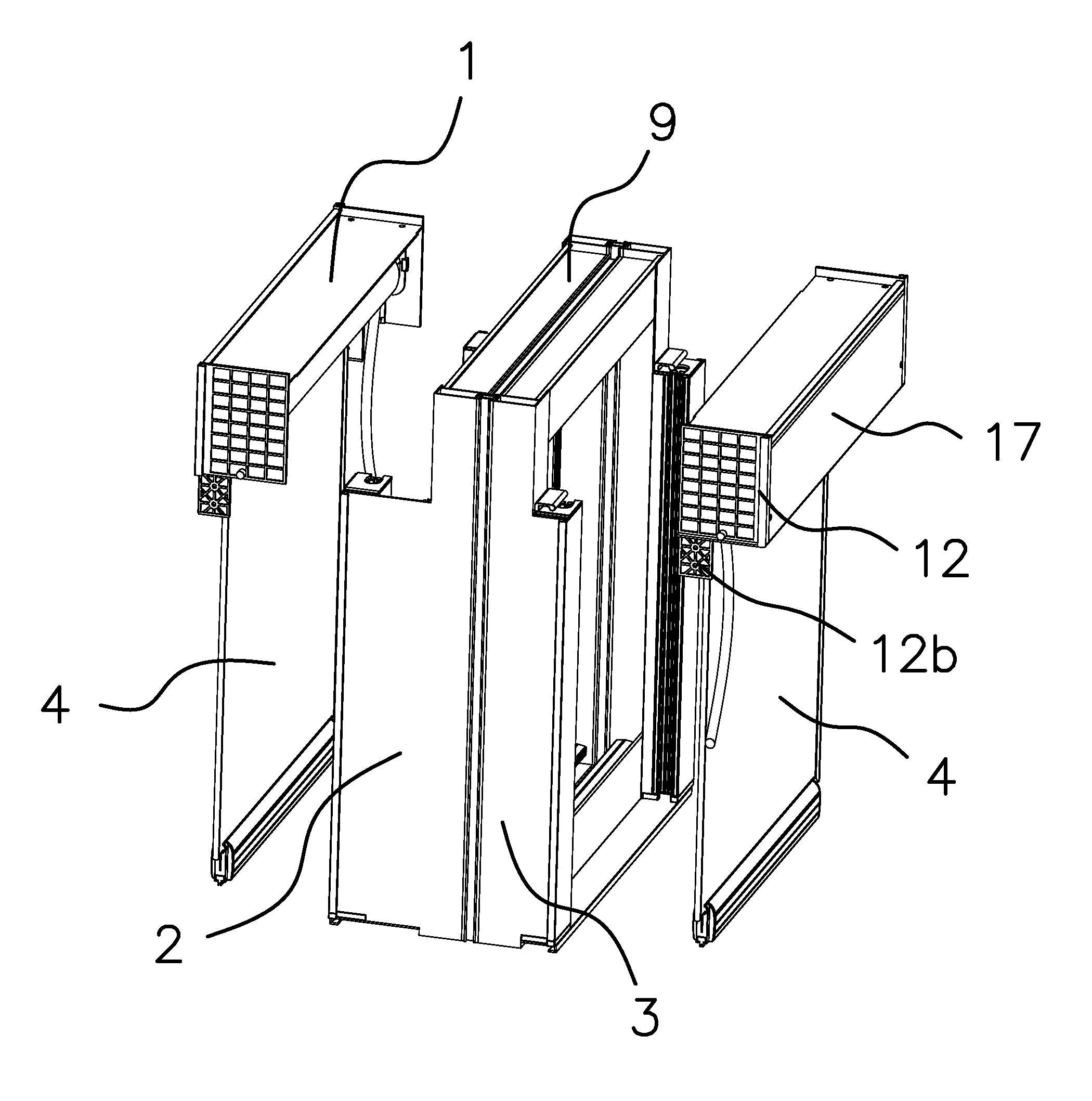
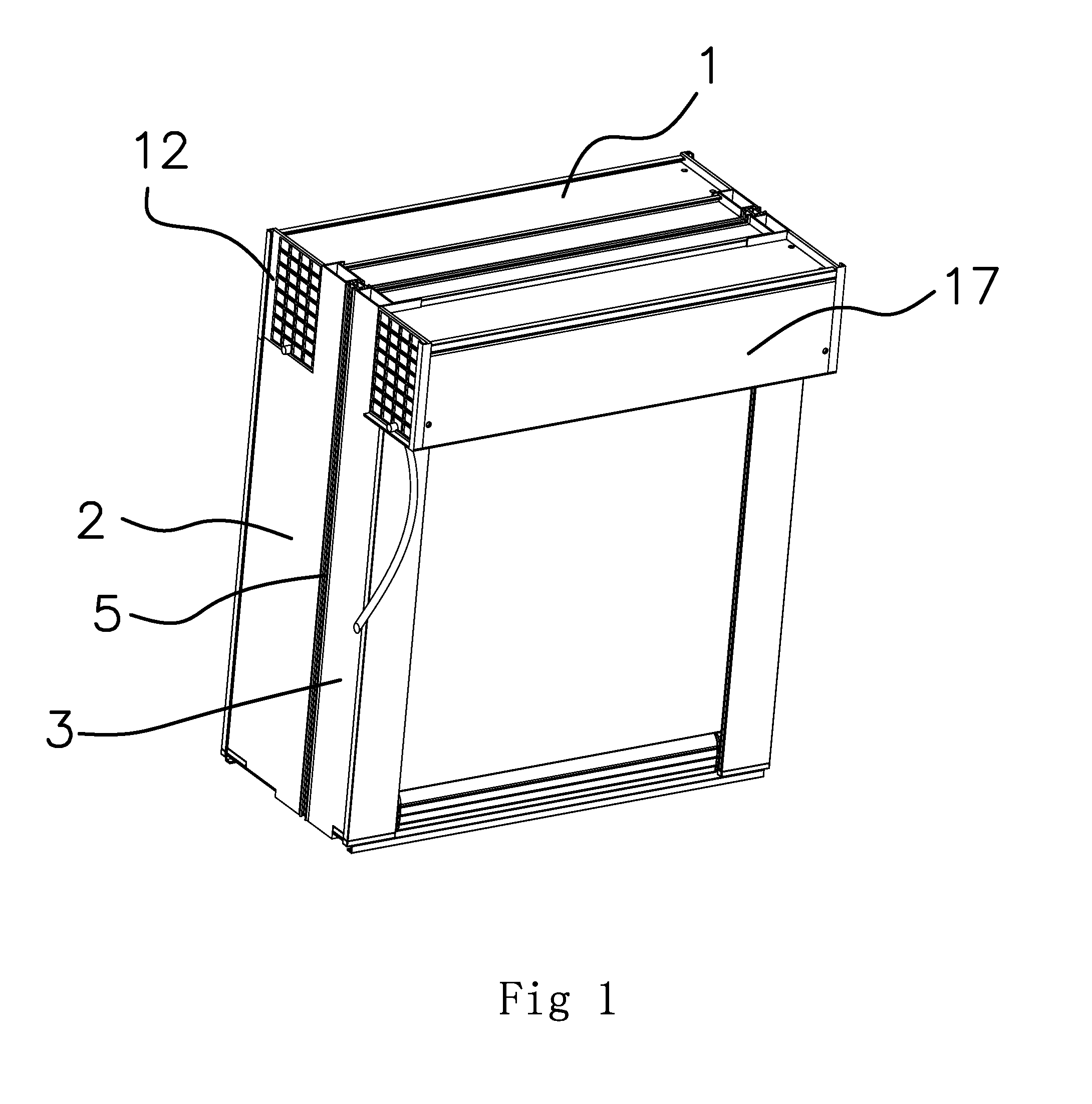
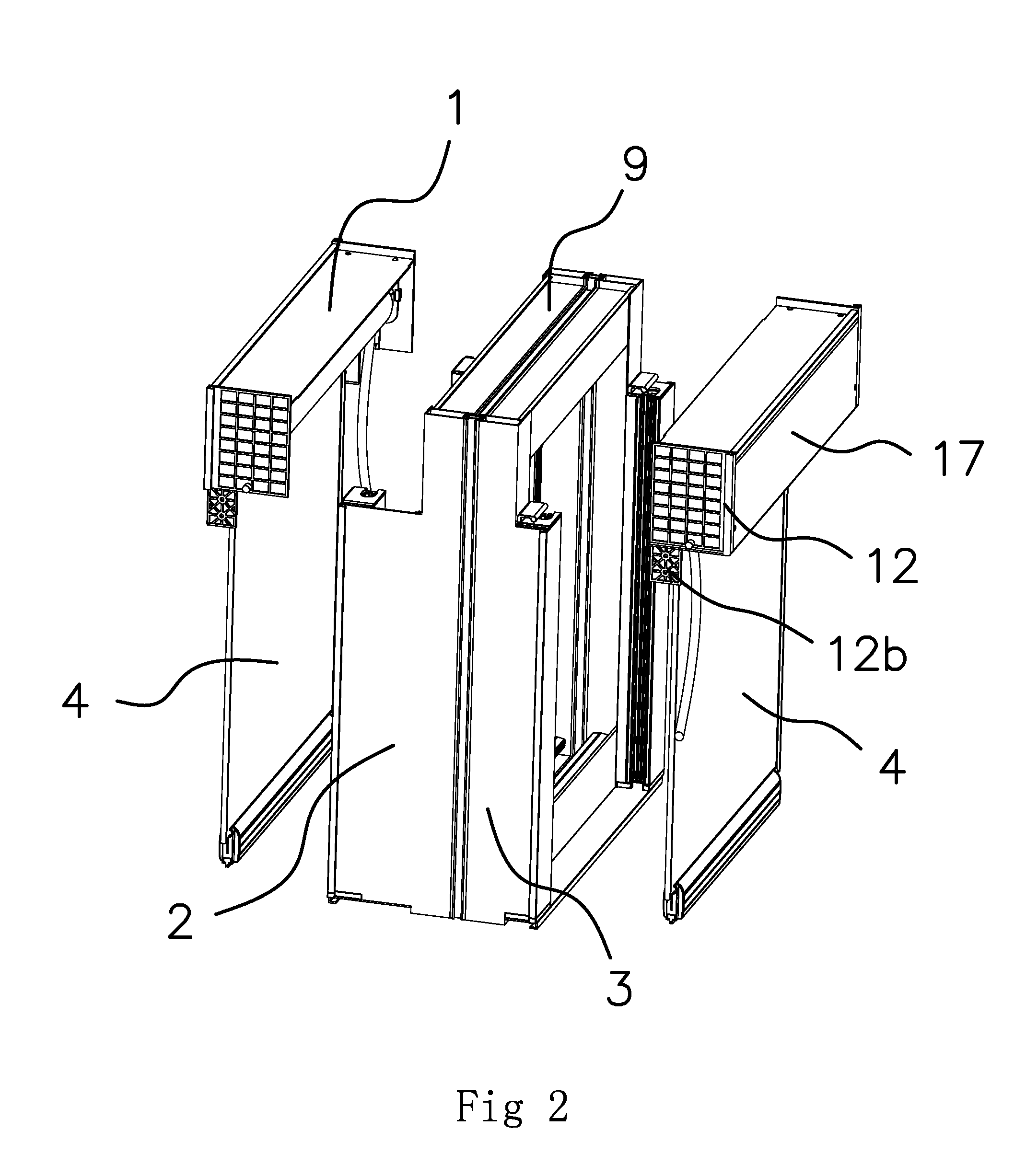
[0065]In this embodiment, an integrated window has front and back window frames, as shown in FIGS. 1-12. The front and back window frames have the same structural principle, for which the structures of the window frames will be specifically described as follows.

[0066]Two front frame bodies 2 are symmetrically located on both sides of the front window frame. The front frame body 2 has a front support portion 2a and a front guide portion 2b. The front frame body is configured as an elongated L-shape. That is to say, the front support portion 2a is vertically connected with the front guide portion 2b, and an indentation 2e is formed above the front support portion 2a and the front guide portion 2b, in which the upper end of the front support portion is located higher than the front guide portion. In this embodiment, the front support portion 2a is integrated with the front guide portion 2b.

[0067]A front window cover 1 is mounted on the front frame bodies 2. The indentation 2e formed b...

second embodiment

[0083]This embodiment is different from the first embodiment in that one of the window frames does not have window covers, curtain cloth or other parts. The structure of the second embodiment will be described below.

[0084]As shown in FIGS. 13-17, the support portion 2a is fixedly connected with a lateral seal via a plastic bar 5. In particular, a first groove 2d is provided on a side of the support portion 2a and a second groove 4a is provided on a side of the lateral seal 4 corresponding to the first groove 2d. Both ends of the plastic bar 5 are inserted into and fixed to the first groove 2d and the second groove 4a respectively. The plastic bar 5 has an I-shape section. In the process of mounting, the lateral seal 4 is firstly aligned with the frame body 2, the plastic bar 5 is then aligned with and inserted into the first groove 2d and second groove 4a, and two long lateral edges of the plastic bar 5 are fixed within the first groove 2d and second groove 4a respectively to connec...

third embodiment

[0091]As shown in FIGS. 18 and 19, the structures and principles of the third embodiment are substantially the same as those of the second embodiment. The third embodiment is merely different from the second embodiment in that the indentation 3 formed between the guide portion 2b and the support portion 2a has a width smaller than that of the window cover 1, because the window frame of this embodiment is mainly applied to inner sun shading windows and the frame body 2 is located within the room and the lateral seal is located outside of the room. In other words, the window cover 1 is positioned inside the room in the third embodiment. As the lateral seals 4 and the frame bodies 2 are mounted within the wall, the frame bodies 2 can not extend beyond the wall for the purpose of attraction and harmony of the whole product. Meanwhile, the area of the window cover 1 can not be overly small as it is provided with a tubular motor. Consequently, the width of the indentation 3 formed between...


PUM


Abstract

The present invention discloses an integrated multi-function window in the technical field of building material, which overcomes the disadvantages of the existing windows, including complicated structures and time, labor and cost consuming double constructions. The integrated multi-function window includes a first window frame having a first window. A first window cover is mounted at the upper part of the first window frame and first telescopic curtain cloth is located within the first window cover. One side of the first window frame is fixedly connected to the second window frame having a second window. The position of the second window is corresponding to that of the first window. The integrated multi-function window has a simple configuration and multiple functions and is of a low cost and improved reliability.

Description

BACKGROUND OF THE INVENTION[0001]1. Field of Invention[0002]The present invention relates to the technical field of building materials, in particular, to an integrated window with energy saving, sun shading, heat insulating and heat preserving functions.[0003]2. Related Art[0004]The energy consumption of buildings now accounts for around 30% of the total energy consumption of the whole country with development of economy, of which the energy consumed by air conditioners account for around fifty percent. It is one of the most direct and effective energy saving means to provide the buildings with sunshades. However, sun-shading products are mounted so separately from the windows of buildings presently in this country that materials are wasted for repeated installation even though the energy saving effect could be achieved to some extent.[0005]To this end, an integrally welding window frame profile for a single sliding window is disclosed in the Chinese Patent Publication No. CN1017878...

Claims


Application Information

Patent Timeline
Patent Type & Authority Applications(United States)
IPC IPC(8): E06B3/67E06B9/42E06B3/66E06B5/00E06B7/28
CPCE06B3/6722E06B5/00E06B9/42E06B3/66E06B7/28E06B9/582E06B2009/17069E06B2009/2452E06B9/581E06B3/26E06B3/46E05Y2900/148E05D15/08E06B9/72E06B2009/587E06B2009/588
Inventor LU, XIANFENGSANG, JIANHUA
Owner NINGBO XIANFENG NEW MATERIAL
Learn More