
Non-Rotating Wellbore Casing Scraper

a scraper and wellbore technology, applied in the direction of fluid removal, wellbore/well accessories, earthwork drilling and mining, etc., can solve the problems of reducing well efficiency, affecting the operation of the well, so as to facilitate scraping and scraping. , the effect of sacrificing the non-rotating utility of the assembly

Inactive Publication Date: 2015-01-29
PENISSON DENNIS JOEL
View PDF1 Cites 33 Cited by
  • Summary
  • Abstract
  • Description
  • Claims
  • Application Information

AI Technical Summary

Benefits of technology

The present invention is an improved non-rotating casing scraper assembly that solves existing strength problems. The assembly is made without any connective joints or threads, making it stronger than previous devices. The mandrel section of the tool body has bearing shoulders that retain the blade carriers and centralizers in place. The blade carriers have blade sockets that allow the blades to be housed in a post-ort perpendicular to the tool body. The blades are biased outward by a spring and prevented from being ejected through the blade sockets. The centralizers keep the blades carriers in the center of the wellbore to facilitate even scraping throughout the length of the wellbore. The diamond-shaped blades produce a balanced non-torque cutting force perfect for pull or push scraping to ins life the entirety of the easing wall.

Problems solved by technology

After drilling on an oil or gas well is concluded there is often a buildup or accumulation of debris and contaminants adhered to the interior surface wall of the wellbore casing.
If the wellbore casing is left unclean, debris and contaminates lining the casing wall could greatly throttle fluid flow and reduce well efficiency.
Accumulated casing debris may also present dangerous well conditions by making wellbore repair more difficult, costly and time-intensive.
While these traditional casing scrapers are effective in vertical and near-vertical wellbores where the forces and pressures are relatively constant and well documented, these traditional rotating scrapers are much less effective and insufficient when the wellbore is deep or near horizontal like those wellbores that are now being drilled.
In such deep wellbores and horizontal wellbores the frictional drag associated with rotating blade scrapers against the casing is unacceptable, as it greatly reduces the efficiency of the drillstring.
These rotating scrapers can also cause long term wear and associated damage to the casing of the wellbore, reducing the life of the well and the costs associated with repair.
These threaded joints weaken the assembly and increase the risk of failures that may ultimately cause the scrapers to disconnect, shear, unthread, or break apart under the high torque encountered during use.
The risk of failure of associated with such non-rotating casing scrapers will increase when such scrapers are used on long and near-horizontal wellbores such as wellbores 10,000 feet or longer now becoming common in the drilling of oil and gas wells.
A further disadvantage of current scraper assemblies is that the alignment and orientation of the scraper blades does not completely eliminate axial rotation of the scraping assembly as it passed through a wellbore.
These rotational forces translate into axial rotation within the scraper assembly, reducing the effectiveness of the non-rotating element of the assembly.
Even slight rotation of a helical blade can cause un-scraped surfaces in the casing as the tool is advanced.
A further disadvantage of previous casing scraper assemblies is their inherent selection of either left-handed or right-handed drilling.
These scraper assemblies rarely afford the flexibility rotating in both directions without altering the equipment.
These scraper assemblies employ slanted grooves or angled cutting surfaces on the scraper blade biased towards one axial direction, which greatly reduces the effectiveness of the assembly when switched between drilling directions.
The inability of the scraper to transition between different drilling directions creates the need for companies to purchase additional equipment and ultimately increases the cost of drilling oil and gas wells while reducing equipment flexibility at drilling sites.

Method used


Image

  • Non-Rotating Wellbore Casing Scraper
  • Non-Rotating Wellbore Casing Scraper
  • Non-Rotating Wellbore Casing Scraper

Examples


Embodiment Construction

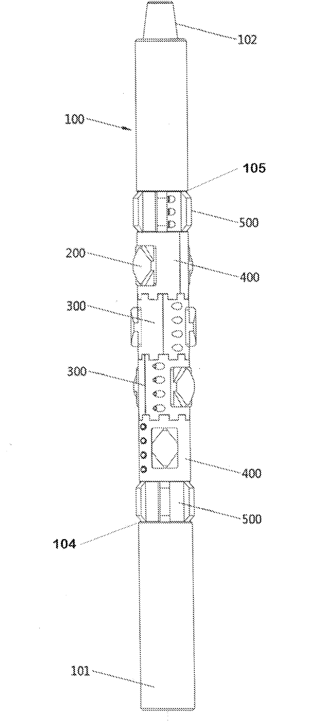
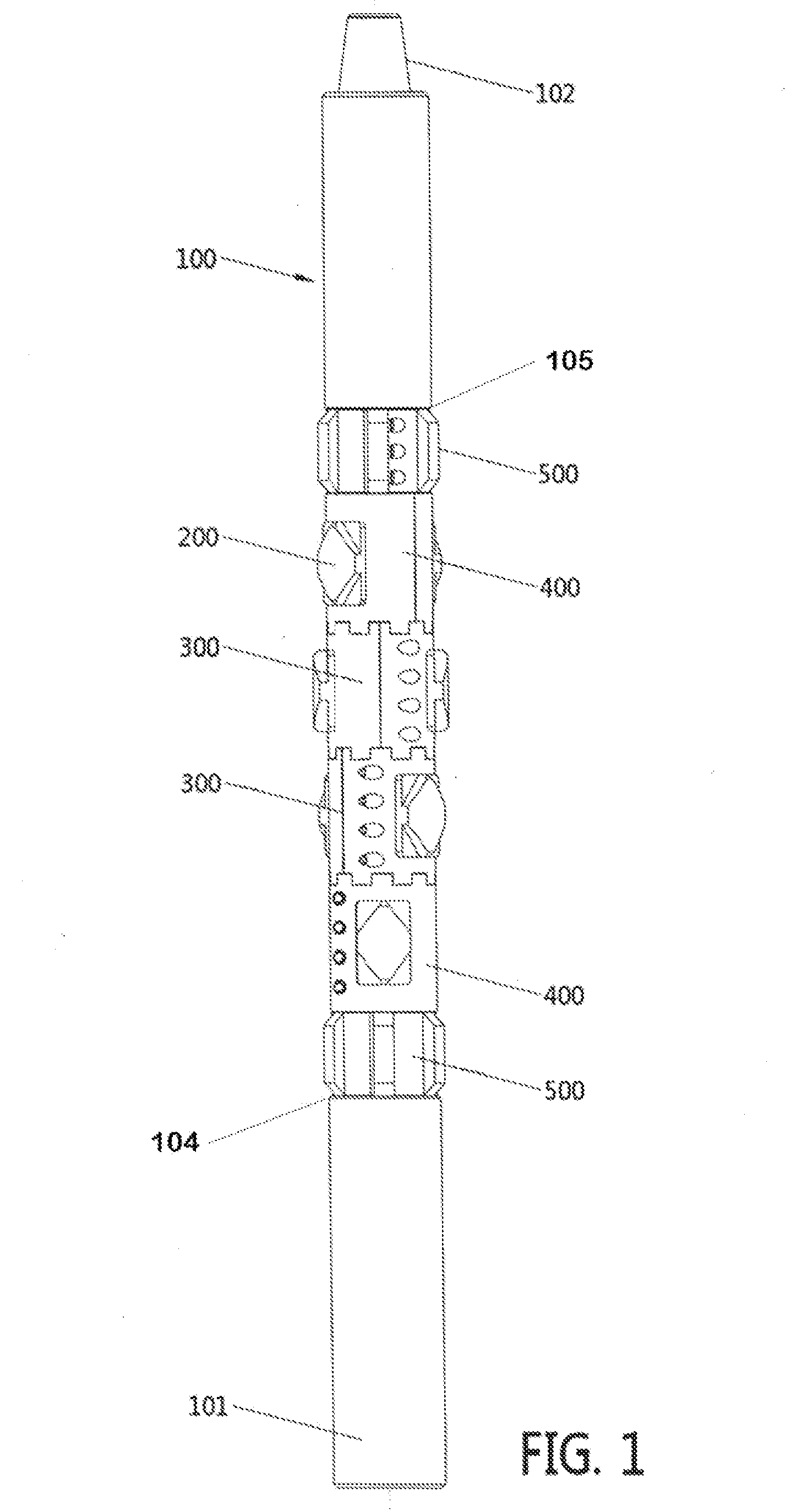
[0021]FIG. 1 shows a longitudinal side view of the casing scraper assembly (10) embodying the disclosed invention. Casing scraper assembly (10) is comprised of a longitudinally extending tubular base or tool body (100) with a longitudinally extending, array of interlocked, blade carriers (300) and (400), each housing a plurality of diamond-shaped symmetrical scraper blades (200), and a plurality of centralizers (500). The blade carriers (300) and (400), each housing blades (200), and the centralizers (500) are mounted to freely rotate axially around tool body (100) independent of the tool body rotation imparted by the drillstring. Blade carriers (300) and (400) are axially oriented around body (100) such that blades (200) are indexed or staggered so that they are not in longitudinal alignment with each other. Centralizers (500) also freely rotate axially around tool body (100) independent of the tool body rotation to keep the casing assembly (10) centralized within the wellbore duri...


PUM


Abstract

A torque resistant casing scraper for attachment to a drillstring is comprised of a one piece tool body having rotationally unrestrained two-piece blade carriers with hardened diamond-shaped cutting blades and rotationally unrestrained two-piece axial centralizers. Adjoining blade carriers and centralizers rotate independently of the drillstring and the blade carriers interlocked to prevent relative rotation between the blade carriers and to index, or orient the cutting blades as desired along the longitudinal axis of the casing scraper. The diamond-shaped cutting blades and the indexed blade carriers allow both right-handed and left-handed drillstring rotation without reducing utility or effectiveness of the scraper. The casing scraper is particularly effective for deep, near-horizontal wellbores.

Description

PRIORITY[0001]This application claims priority to U.S. provisional application Ser. No. 61 / 857,475 filed Jul. 23, 2013 entitled “Non-Rotating Wellbore Casing Scraper”, the entire content of which is incorporated by reference.FIELD OF THE INVENTION[0002]This invention relates to an improved tool for cleaning wellbore casings. More particularly, it relates to an improved casing scraper mounted to clean and remove debris from the interior surface of wellbore casing pipe with a casing scrapper having a series of indexed non-rotating blades.BACKGROUND OF THE INVENTION[0003]After drilling on an oil or gas well is concluded there is often a buildup or accumulation of debris and contaminants adhered to the interior surface wall of the wellbore casing. If the wellbore casing is left unclean, debris and contaminates lining the casing wall could greatly throttle fluid flow and reduce well efficiency. Accumulated casing debris may also present dangerous well conditions by making wellbore repair...

Claims


Application Information

Patent Timeline
IPC IPC(8): E21B37/02
CPCE21B37/02
Inventor PENISSON, DENNIS JOEL
Owner PENISSON DENNIS JOEL
Features
  • Generate Ideas
  • Intellectual Property
  • Life Sciences
  • Materials
  • Tech Scout
  • Unparalleled Data Quality
  • Higher Quality Content
  • 60% Fewer Hallucinations
Learn More