Blade gripping tool and device

a blade and gripping technology, applied in the direction of load-engaging elements, transportation and packaging, etc., can solve the problems of time-consuming, difficult to control, and manual wounding of straps around the rotor blade, so as to facilitate the positioning and orientation process of the blade gripping device, reduce the danger of operation, and easy to control

Active Publication Date: 2015-01-29
SIEMENS GAMESA RENEWABLE ENERGY AS
View PDF11 Cites 19 Cited by
  • Summary
  • Abstract
  • Description
  • Claims
  • Application Information

AI Technical Summary

Benefits of technology

[0012]As in the above-mentioned state of the art, the blade gripping device comprises a sling-conveying element and a sling-receiving element which interact: the sling-conveying element conveys the connection means of the sling and thus the sling itself (by tearing the sling along the path of travel) to the sling-receiving element along a two-dimensional path of travel, i.e. along a path of travel which is all along one, vertical, plane. Herein lays the main difference in comparison with the state of the art, which makes the movement of the sling much simpler and which safes a lot of space during the connection of the rotor blade to the blade gripping tool (and blade gripping device).
[0074]Further, the first frame comprises a rectangular carrying structure with at least four connectors for connection to a lifting device, which connectors are positioned essentially at the corners of the rectangular structure. This means that the connection to the lifting device such as a crane is not just realized at one point (which would imply very high loads at such connector), or at two or three points (which would still imply high loads and a substantial instability of the blade gripping device when suspended). Instead, a very stable, symmetric connection structure is used which can effectively help to horizontally align the blade gripping device as well as the blade assembly (with the rotor blade). Furthermore, with such device with connectors essentially at corners of the first frame full use can be made of the extension of the first frame which helps to even further stabilize the blade gripping device (and blade assembly) when suspended.

Problems solved by technology

The assembly of rotor blades on wind turbines and their transport to and fro is a time-consuming, relatively dangerous and also costly task.
Further, the straps have to be wound around the rotor blade and also unwound manually which involves work at substantial heights.
Such dismounting system is still rather complex to handle.
In addition, less or no relatively weak interconnections (such as the hinges in the state of the art) are necessary, which would not just be a potential danger during operation but which also would have to be controlled separately during the movement of the sling-conveying element.
For instance, optical markers may not be so convenient if the device is often operated in foggy conditions, audible markers may then be more helpful.
Firstly, the shape of the rotor blade has to match in the right place with the shape of the blade gripping tools. As modern rotor blades do not have the same cross-sectional extensions all along their longitudinal extension the shape of the blade gripping tools may not fit with the rotor blade at any location along that longitudinal extension. The right place is thus such a location of the rotor blade at which the inner shape of the blade gripping tool can be fit onto the outer shape of the rotor blade.
Secondly, the location at the rotor blade at which the blade gripping tool grips it must be matched with other locations of the rotor blade at which other blade gripping tools grip the rotor blade. In essence, all blade gripping tools of the blade gripping assembly are positioned such that they can grip a part of the rotor blade. Further, they are positioned such that in combination, they grip the rotor blade firmly in an essentially horizontal position. This way, assembly and / or disassembly of the rotor blade at the rotor of a wind turbine is facilitated as the rotor blade is aligned in the position in which it can be assembled and / or disassembled on the rotor's hub.
Thirdly, the centre of gravity of the rotor blade is essentially placed below or above the centre of gravity of the blade gripping device. This helps to avoid instabilities during transport of the rotor blade by means of the blade gripping device.
This means that the connection to the lifting device such as a crane is not just realized at one point (which would imply very high loads at such connector), or at two or three points (which would still imply high loads and a substantial instability of the blade gripping device when suspended).

Method used


Image

  • Blade gripping tool and device
  • Blade gripping tool and device
  • Blade gripping tool and device

Examples


first embodiment

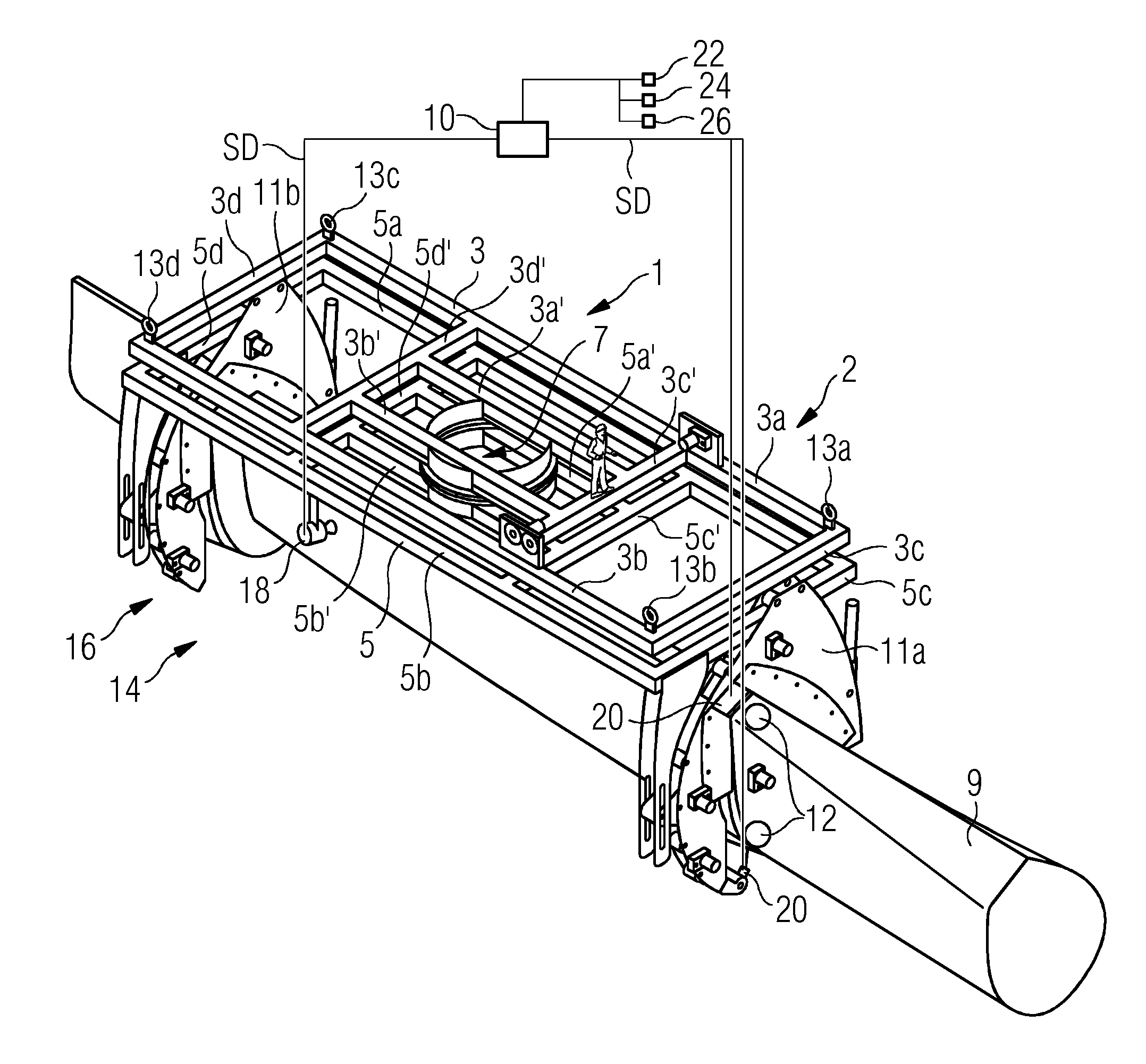
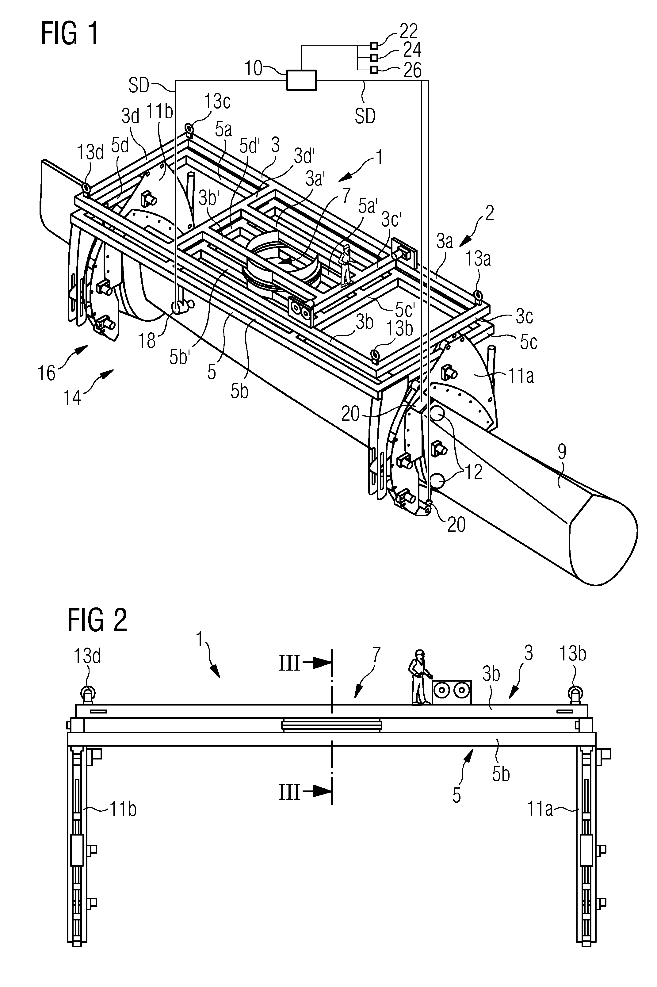
[0099]FIGS. 1 and 2 show a blade gripping device 1 according to the invention. It grips a rotor blade 9 of a wind turbine (not shown). The blade gripping device 1 comprises a first frame 3 and a second frame 5 which are interconnected via a swivel connection 7. The first, upper, frame 3 comprises an essentially rectangular, namely oblong shape which is defined by a first outer longitudinal beam 3a and a parallel second outer longitudinal beam 3b and a first outer cross beam 3c and a second outer cross beam 3d parallel to the first outer cross beam 3c, which beams 3a, 3b, 3c, 3d are connected to each other at corners of the first frame 3. In addition, the first frame 3 comprises in its middle part two parallel inner cross beams 3c′, 3d′ which have essentially the same length as the first and second outer cross beams 3c, 3d, to which they are parallel, and two parallel inner longitudinal beams 3a′, 3b′ which are parallel to the two outer longitudinal beams 3a, 3b but only have about h...

second embodiment

[0117]FIGS. 13 and 14 show a sling handover mechanism 17′. Most of its elements correspond directly with those of the embodiment explained with reference to FIGS. 1 to 12, so that only different elements will be described here. A first difference is the sling-receiving element 27′ which is here realized to comprise a hydraulic actuator right aside the other (known) parts of the sling-receiving element 27 according to the previous embodiment. Another difference is a hinged guidance shoe 65 with a soft and flexible contact surface 69 to the rotor blade 9. When looking at the inside view of FIG. 14 the function of this guidance shoe 65 becomes clearer:

[0118]Whereas the guidance shoe 65 is in a contact position with the rotor blade in FIG. 13, it is tilted back via a tilting axis 70 (assisted by an actuator, e.g. a spring—not shown) into a retracted position corresponding to an open position of the sling handover mechanism 17′. A stopper 71 stops that retraction movement of the guidance...


PUM


Abstract

A blade gripping tool of a blade gripping device for gripping a rotor blade, in particular a rotor blade of a wind turbine is provided. The tool comprises a sling and an automatic sling handover mechanism comprising a sling-conveying element and a sling-receiving element, whereby the sling-conveying element is realized to convey a connection means of the sling along a two-dimensional predefined path of travel around a part of the rotor blade towards the sling-receiving element to connect to a receptor of the sling-receiving element. The invention also concerns a method of gripping a rotor blade, in particular a rotor blade of a wind turbine by means of a number of blade gripping tools.

Description

CROSS-REFERENCE TO RELATED APPLICATIONS[0001]This application claims priority to EP Application No. 13178402.7, having a filing date of Jul. 29, 2013, the entire contents of which are hereby incorporated by reference.FIELD OF TECHNOLOGY[0002]The following relates to a blade gripping tool of a blade gripping device for gripping a rotor blade, in particular a rotor blade of a wind turbine, i.e. a rotor blade of a large size such as of 50 metres in length or longer. Such gripping device is realized for a transport of the rotor blade to and / or from an assembly site, in particular an assembly site of a wind turbine. The gripping device thus serves to grip the rotor blade firmly so that it can be transported (i.e. raised) to the nacelle of the wind turbine and / or lowered from the latter. The invention also concerns a method of gripping a rotor blade.BACKGROUND[0003]The assembly of rotor blades on wind turbines and their transport to and fro is a time-consuming, relatively dangerous and al...

Claims


Application Information

Patent Timeline
Patent Type & Authority Applications(United States)
IPC IPC(8): B66C1/10B66C1/18
CPCB66C1/18B66C1/108
Inventor HANSEN, STEEN MATTRUPMOELLER, JESPERSVINTH, KENNETH HELLIGSOE
Owner SIEMENS GAMESA RENEWABLE ENERGY AS
Why Eureka
Try Eureka