Electronic device module

Active Publication Date: 2015-01-29
JAPAN AVIATION ELECTRONICS IND LTD
View PDF2 Cites 57 Cited by
  • Summary
  • Abstract
  • Description
  • Claims
  • Application Information

AI Technical Summary

Benefits of technology

[0007]The present invention has been made to solve the above-described prior art problems and an object of the present inventio

Problems solved by technology

However, the in-vehicle camera is susceptible to electromagnetic disturbance or the like and an image quality may be deteriorated.
Therefore, the spring contacts may deteriorate during a long-term use

Method used


Image

  • Electronic device module
  • Electronic device module
  • Electronic device module

Examples


Example

Embodiment 1

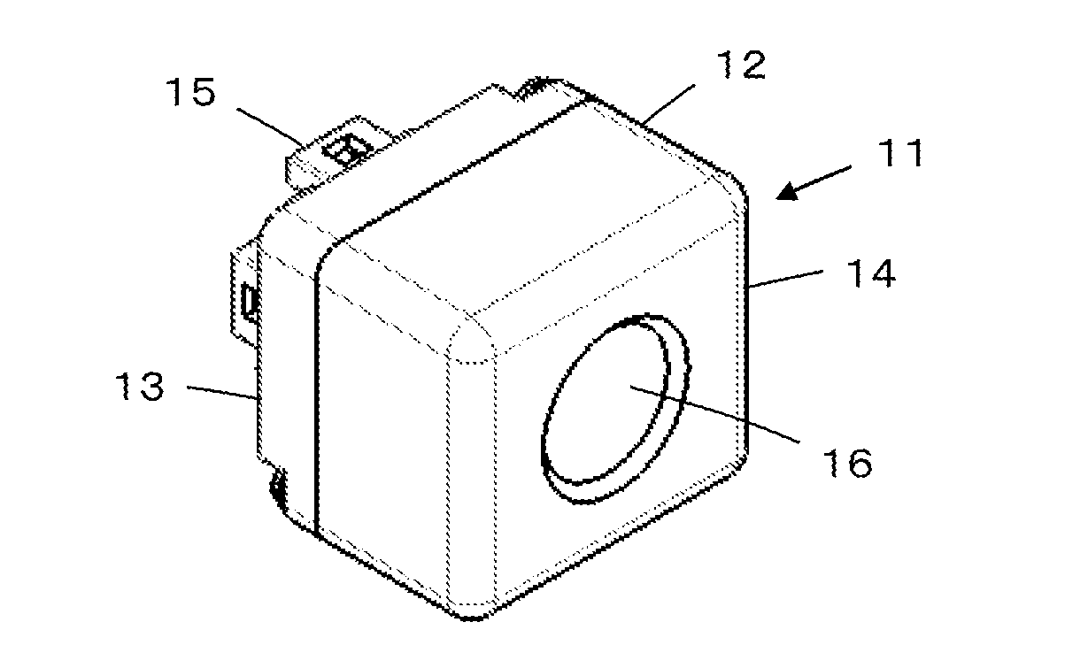
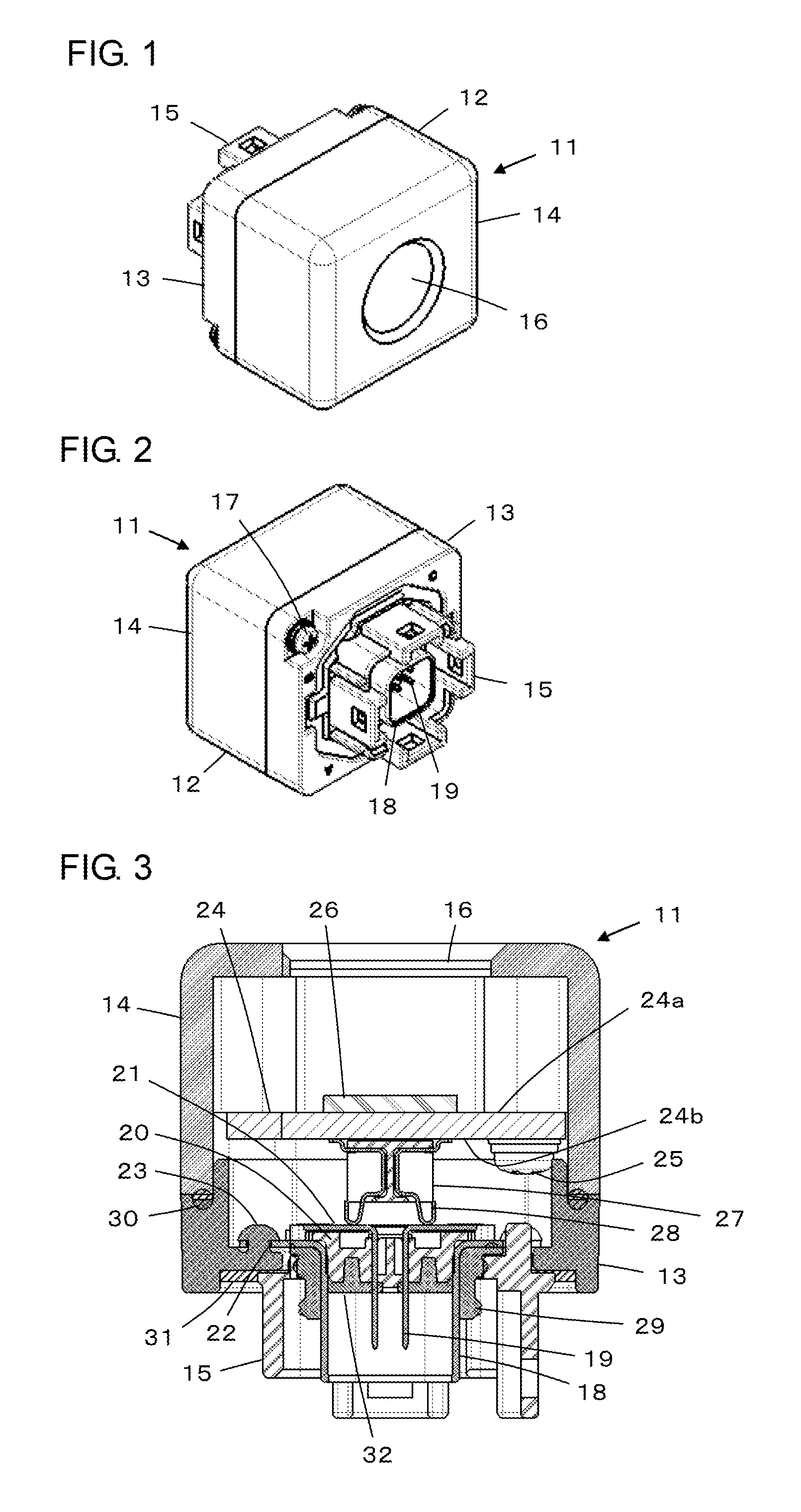
[0032]FIG. 1 shows the configuration of an electronic device module 11 according to Embodiment 1 of the invention. The electronic device module 11 is applied to an in-vehicle camera module attached to a part of a body of an automobile and includes a metallic casing 12 having the shape of a rectangular parallelepiped. The casing 12 includes a casing body 13 and a cover member 14 joined to a front side of the casing body 13, and a part of an outer housing 15 made of an insulating material such as resin protrudes on a back side of the casing body 13. A lens portion 16 of the in-vehicle camera is formed at a central portion of a front face of the cover member 14.

[0033]As shown in FIG. 2, the cover member 14 is fixed to the casing body 13 with screws 17. A part of a metallic ground shell 18 is disposed inside the outer housing 15 protruding on the back side of the casing body 13. In addition, connector terminals 19 for external device connection are exposed inside the ground ...

Example

Embodiment 2

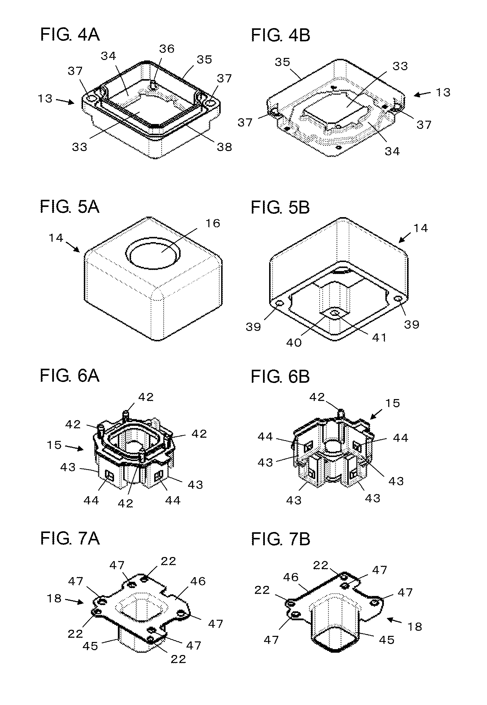
[0070]In the above-described Embodiment 1, as shown in FIG. 12, each boss 36 of the casing body 13 has a columnar shape and each boss insertion portion 22 of the ground shell 18 is formed of a circular hole having a slightly larger diameter than that of the boss 36. However, the invention is not limited to this.

[0071]For example, as shown in FIG. 19A, a cylindrical boss 36a with a hollow interior replacing the columnar boss 36 may pass through the boss insertion portion 22 formed of a circular hole, and the head of the boss 36a and the coated layer of the ground shell 18 positioned on the periphery of the boss insertion portion 22 may be welded to each other.

[0072]As shown in FIG. 19B, each boss 36 may be fitted into a boss insertion portion 22a formed of a cutout having an arc-like portion corresponding to the curvature of the columnar boss 36 instead of the boss insertion portion 22 formed of a circular hole. Also in this case, by welding the head of the boss 36 and th...


PUM


Abstract

An electronic device module includes a metallic casing having at least one boss formed therein, an electronic device unit placed inside the casing, connector terminals for external device connection electrically connected to the electronic device unit, and a metallic ground shell disposed so as to surround the connector terminals, having a front surface covered with a metal coated layer and including at least one boss insertion portion formed, a head of the at least one boss inserted into the at least one boss insertion portion and the coated layer positioned on a periphery of the corresponding at least one boss insertion portion being welded to each other to electrically connect and fix the ground shell to the casing.

Description

BACKGROUND OF THE INVENTION[0001]The present invention relates to an electronic device module and more specifically to an electronic device module in which an electronic device unit to be connected to an external device via connector terminals is placed in a casing.[0002]An in-vehicle camera for capturing a rear or front view of a vehicle and displaying the resulting image on a monitor disposed on an instrument panel is often used for such purposes as car parking assistance and improvement of a driving safety. Such an in-vehicle camera is attached to a part of a vehicle body and is connected to the monitor near a driver's seat via a connector and a wire harness, and image signals acquired by an image sensor in the camera such as a CMOS (complementary metal-oxide semiconductor) or a CCD (charge-coupled device) are transmitted to the monitor. However, the in-vehicle camera is susceptible to electromagnetic disturbance or the like and an image quality may be deteriorated.[0003]Then, fo...

Claims


Application Information

Patent Timeline
IPC IPC(8): H04N5/225H04N7/18
CPCH04N7/18H04N5/2252H01R4/029H01R13/6581H01R2201/26H01R13/5216H01R4/06H04N23/57H01R13/6485H01R33/76H04N23/51
Inventor UCHIYAMA, YUICHIHIGUCHI, MASAOISHIWA, TADASHINITTA, MASAYOSHI
Owner JAPAN AVIATION ELECTRONICS IND LTD
Why Eureka
Try Eureka