
Bearing arrangement of a wind turbine and method for adjusting the preload of a bearing arrangement

a technology for wind turbines and bearings, applied in bearings, roller bearings, shafts, etc., can solve the problems of component overload and damage, affecting the strain on and function of all components, and high consequential costs, so as to improve the bearing arrangement

Active Publication Date: 2015-01-29
EOLOTEC
View PDF7 Cites 32 Cited by
  • Summary
  • Abstract
  • Description
  • Claims
  • Application Information

AI Technical Summary

Benefits of technology

The present invention aims to enhance the bearing arrangement for supporting the rotor of a wind turbine.

Problems solved by technology

One of the technical challenges with wind turbines of this type, which are typically designed for electrical output ranging in the several MW, is providing a bearing that can satisfy the high technological demands, such as high flexural stiffness, play-free bearing, low-wear kinematics as well as being as simple as possible to assembly while offering high efficiency at the same time.
When operating, modern wind turbines are subjected to a host of load fluctuations and environmental influences which considerably impact the strain on and function of all components.
These fluctuations can lead to component overload and damage and thereby high consequential expenses.
This problem is likewise seen in what is referred to as the main bearing of the wind turbine, which constitutes the linking member between the rotating system and the stationary system.
This results in a conservative and thus a not especially dimensioning of the main bearing.
In addition to these economic aspects, this type of overdimensioning results in an increased frictional torque compared to that of a normal design, which in turn results in shorter service lives, increased breakaway torque at low wind velocities and increased strain on materials and construction elements.

Method used


Image

  • Bearing arrangement of a wind turbine and method for adjusting the preload of a bearing arrangement
  • Bearing arrangement of a wind turbine and method for adjusting the preload of a bearing arrangement
  • Bearing arrangement of a wind turbine and method for adjusting the preload of a bearing arrangement

Examples


Embodiment Construction

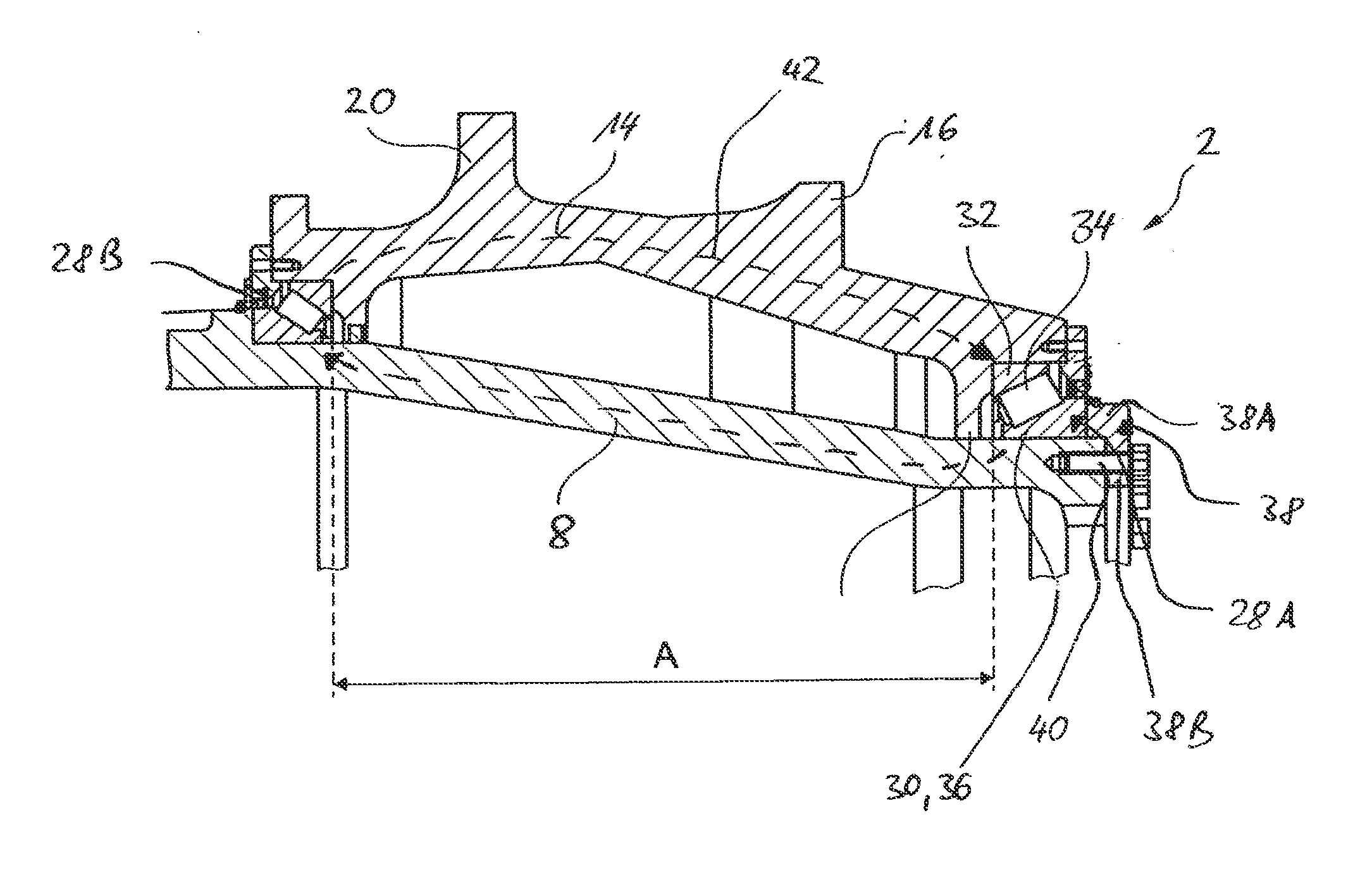
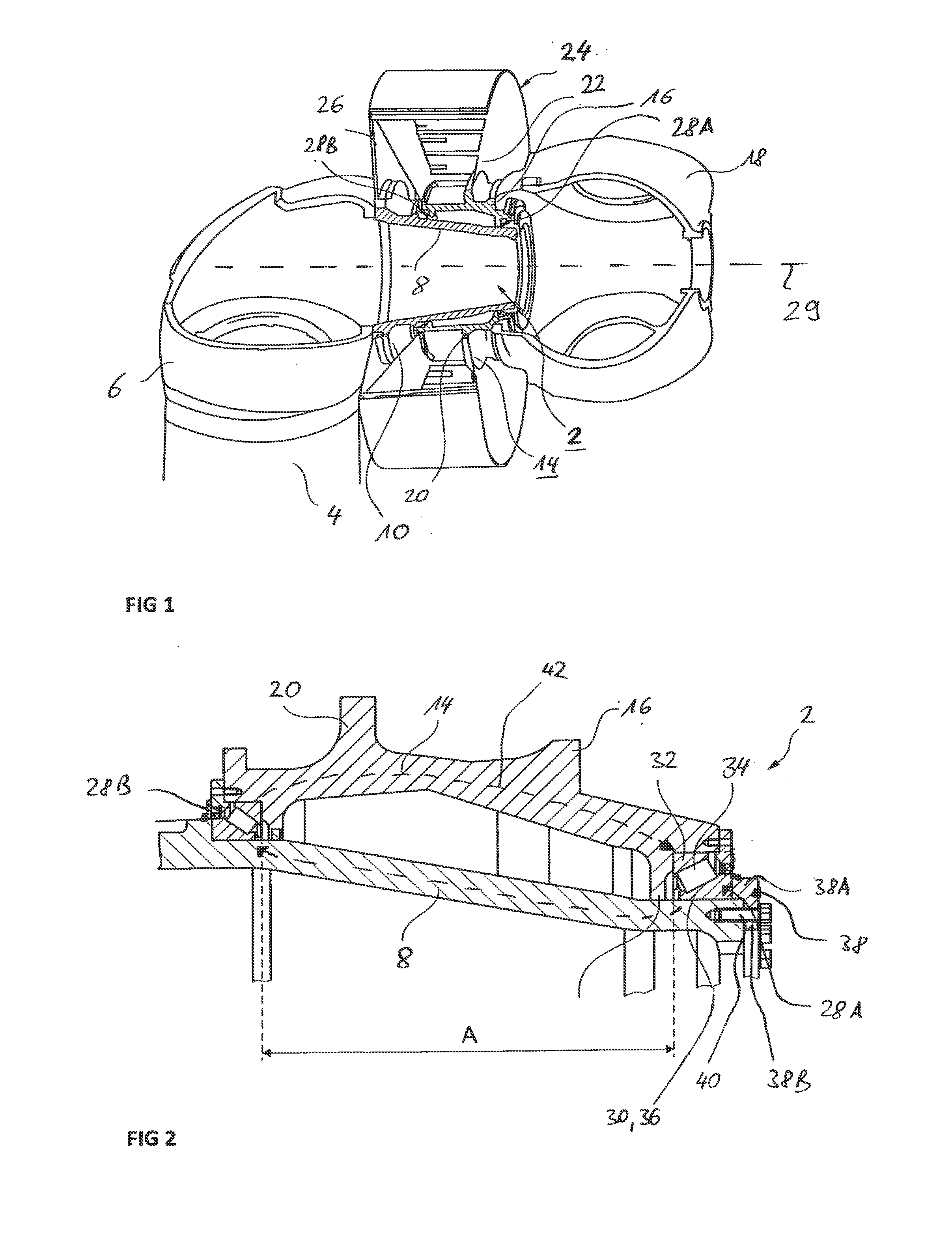
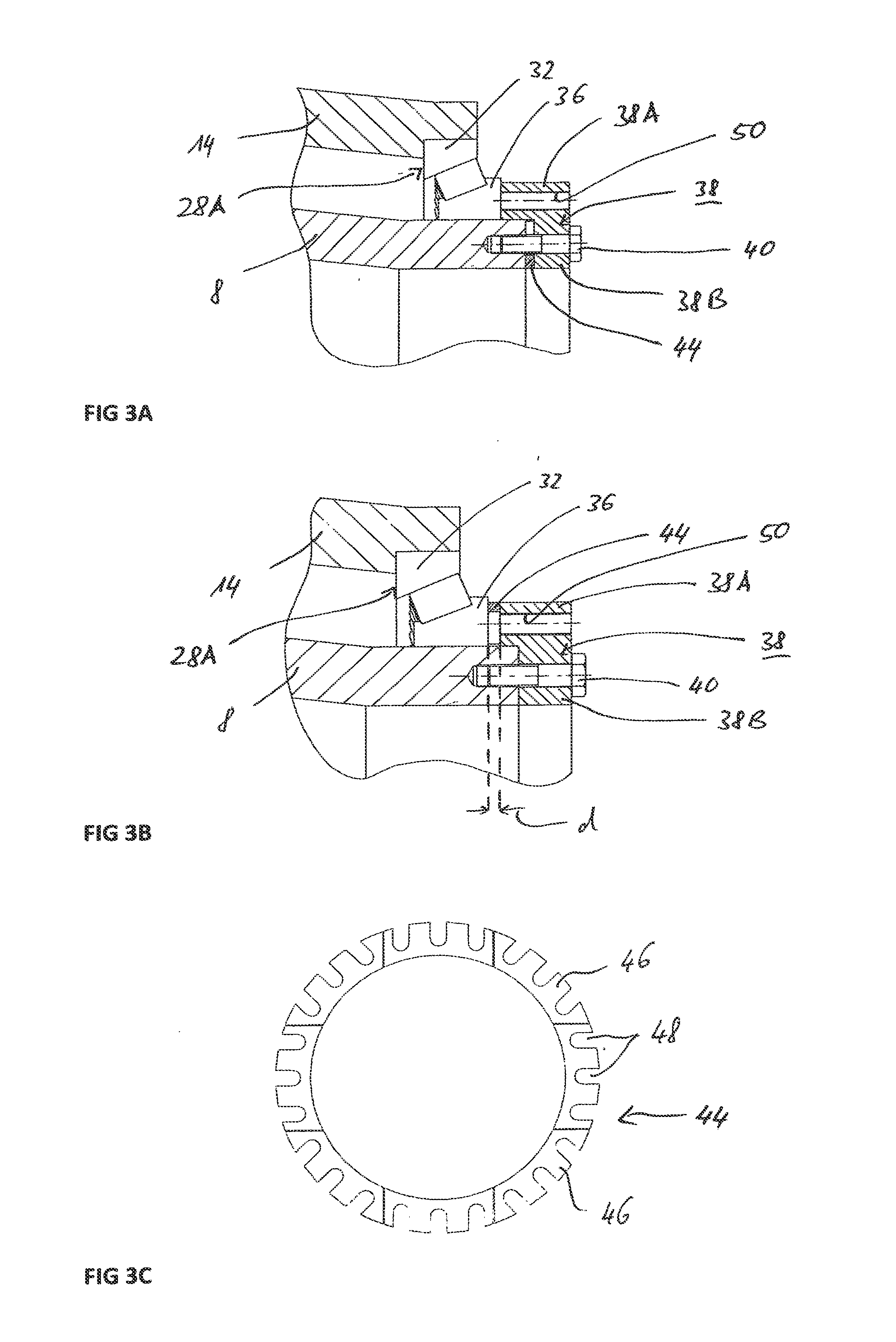
[0051]FIG. 1 shows a cutout of a wind turbine with a bearing arrangement 2 as illustrated enlarged and in greater detail in FIG. 2. In the wind turbine a rotatable gondola constituting a machine carrier 6 is fastened to an upper front end of a tower 4. Attached this gondola via a stator flange 10 is the bearing arrangement 2 with a stator unit 8. This flange is a ring flange running circumferentially around a front end side. Mounted circumferentially around the stator unit 8 is a rotor unit 14 to which a rotor hub 18 is fastened via a rotor flange 16 opposite the tower 4. Rotor blades (not further illustrated) are attached to this hub. Realized on the circumference side of the rotor unit 14 and between the two flanges 10, 16 is a generator flange 20 via which a rotor 22 of a generator 24 is fastened. In addition, a stator 26 of the generator 24 is fastened via the stator flange 10. The rotor unit 14 is mounted on the stator unit 8 via two bearings, specifically a rotor-side bearing ...


PUM


Abstract

To facilitate adjusting a bearing arrangement, particularly in a wind turbine, for different operating situations, the bearing arrangement has an adjusting device with which the bearing preload can be adjusted starting from a base preload. This can allow, for example signs of wear to be compensated, manufacturing tolerances or design inaccuracies to be corrected and in particular current loading states to be addressed. This design avoids the otherwise usual overdimensioning of the bearing arrangement, thereby increasing the efficiency of the wind turbine as well as the service life of the bearing arrangement.

Description

[0001]This nonprovisional application is a continuation of International Application No. PCT / EP2013 / 001053, which was filed on Apr. 10, 2013, and which claims priority to German Patent Application No. 10 2012 206 113.4, which was filed in Germany on Apr. 13, 2012, and which are both herein incorporated by reference.BACKGROUND OF THE INVENTION[0002]1. Field of the Invention[0003]The invention relates to a wind turbine bearing arrangement that is designed as a main bearing for a rotor of the wind turbine, as well as a method for adjusting a preload of a bearing arrangement of the type specified.[0004]2. Description of the Background Art[0005]Wind turbines generally feature a turbine, at the front end of which is arranged a rotatable gondola which constitutes a machine carrier. On the gondola, a rotor hub is mounted rotatably around a rotational axis, with rotor blades being secured to the hub. Wind turbines can either employ a direct drive concept, according to which the rotational mo...

Claims


Application Information

Patent Timeline
IPC IPC(8): F03D11/00F16C41/02F16C19/38
CPCF03D11/0008F16C41/02F16C19/38F16C37/007F16C25/06F16C2300/14F16C2360/31F16C2229/00F16C2240/14F05B2240/50F16C19/364F16C19/548F03D80/70F16C25/083Y02E10/72Y02P70/50
Inventor PICK, MATHIASLOSERT, WOLFGANG
Owner EOLOTEC
Learn More