Optical transmitter, optical communication system, and optical communication method

a technology of optical communication system and optical transmitter, which is applied in the direction of electromagnetic transmission, multiplex communication, electrical apparatus, etc., can solve the problems of reducing the operation speed of electric devices, and unable to achieve the effect of reducing the symbol ra

Active Publication Date: 2015-01-29
NEC CORP
View PDF13 Cites 4 Cited by
  • Summary
  • Abstract
  • Description
  • Claims
  • Application Information

AI Technical Summary

Benefits of technology

[0032]According to an optical transmitter, an optical communication system, and an optical communication method of the present invention, it becomes possible to regenerate transmitting signals without depending on modulation systems for the optical phase modulation in a polarization multiplexed optical communication system employing the optical digital coherent communication system.

Problems solved by technology

If the BPSK system is employed, it is impossible to obtain the effect of reducing a symbol rate because a single bit is allocated to only one type of optical phase.
Since a symbol rate (baud rate) of the optical signal becomes half adversely in such case, it is possible to reduce the operation speed of electric devices.

Method used


Image

  • Optical transmitter, optical communication system, and optical communication method
  • Optical transmitter, optical communication system, and optical communication method
  • Optical transmitter, optical communication system, and optical communication method

Examples


first exemplary embodiment

The First Exemplary Embodiment

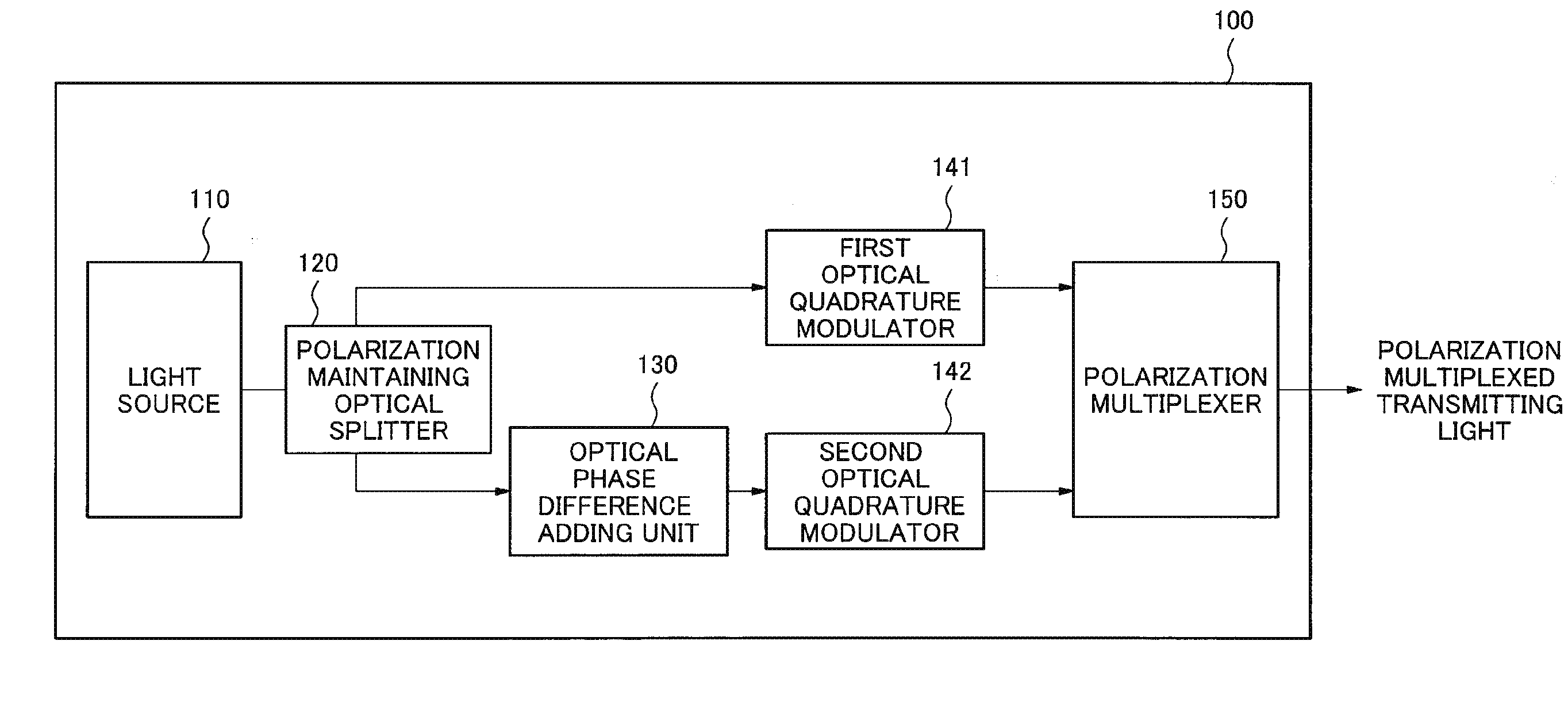
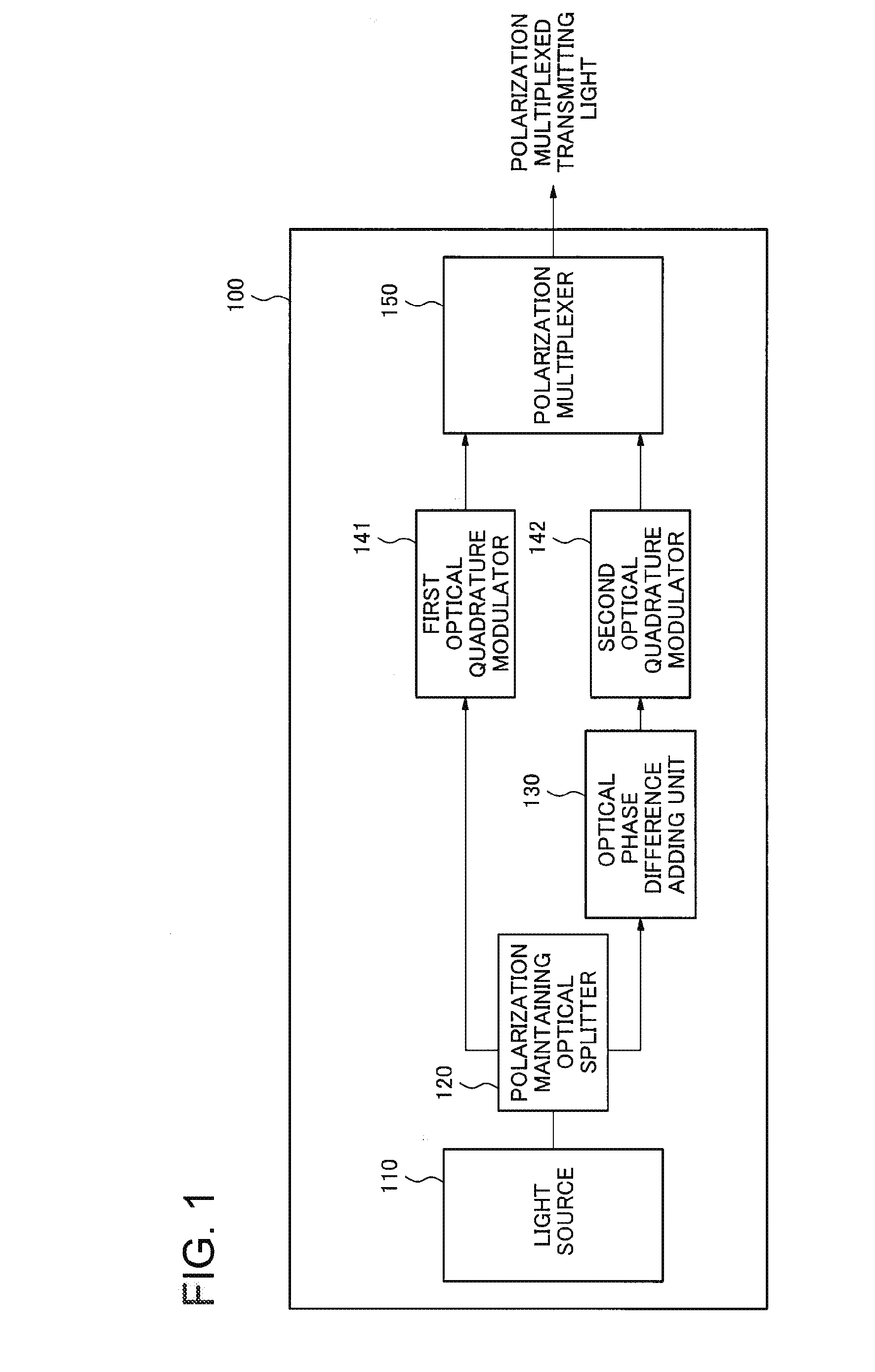
[0042]FIG. 1 is a block diagram illustrating a configuration of an optical transmitter 100 in accordance with the first exemplary embodiment of the present invention. The optical transmitter 100 is used in a polarization multiplexed optical communication system employing the optical digital coherent communication system. As shown in FIG. 1, the optical transmitter 100 includes a light source 110, a polarization maintaining optical splitter 120, an optical phase difference adding unit 130, a first optical quadrature modulator 141, a second optical quadrature modulator 142, and a polarization multiplexer 150.

[0043]The polarization maintaining optical splitter 120 splits a continuous light beam transmitted by the light source 100 into a first continuous light beam and a second continuous light beam. The optical phase difference adding unit 130 adds an optical phase difference varying temporally between the first continuous light beam and the second continu...

second exemplary embodiment

The Second Exemplary Embodiment

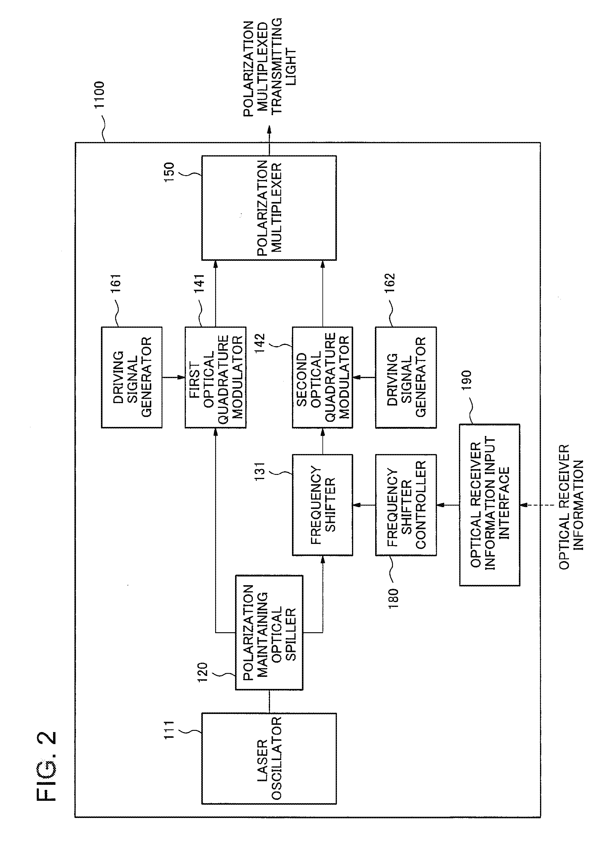
[0048]Next, the second exemplary embodiment of the present invention will be described. FIG. 2 is a block diagram illustrating a configuration of an optical transmitter 1100 included in an optical communication system in accordance with the present exemplary embodiment. FIG. 3 is a block diagram illustrating a configuration of an optical receiver 1200 included in the optical communication system in accordance with the present exemplary embodiment. The optical communication system in accordance with the present exemplary embodiment is a polarization multiplexed optical communication system employing the optical digital coherent communication system. The optical transmitter 1100 transmits polarization multiplexed transmitting light. The optical receiver 1200 receives the polarization multiplexed transmitting light beam, performs the coherent detection of the received light, and demodulates detected signals by means of the digital signal processing.

[0049]...


PUM


Abstract

It becomes difficult to regenerate transmitting signals depending on modulation systems for the optical phase modulation in a polarization multiplexed optical communication system employing the optical digital coherent communication system, therefore, an optical transmitter according to an exemplary aspect of the invention includes first optical quadrature modulation means for performing a phase modulation on a first continuous light beam and outputting a first transmitting light beam; second optical quadrature modulation means for performing a phase modulation on a second continuous light beam belonging in the same frequency band as that of the first continuous light beam and outputting a second transmitting light beam; optical phase difference adding means for adding an optical phase difference varying temporally between the first transmitting light beam and the second transmitting light beam; and polarization multiplexing means for polarization-multiplexing the first transmitting light beam and the second transmitting light beam in the state where their polarizations are made to be orthogonal to each other and outputting a polarization multiplexed transmitting light beam.

Description

TECHNICAL FIELD[0001]The present invention relates to optical transmitters, optical communication systems, and optical communication methods, in particular, to an optical transmitter, an optical communication system, and an optical communication method which employ a polarization multiplexing / demultiplexing system.BACKGROUND ART[0002]Since the traffic volume in the backbone networks has been rapidly increasing due to the growth of the Internet, an ultra-high-speed such as 100 Gbps and long-haul optical communication system has been desired. As a technology to realize such an ultra-high-speed and long-haul optical communication system, an optical phase modulation system and a polarization multiplexing / demultiplexing technology which utilize a digital signal processing technology have been attracting attention.[0003]The optical phase modulation system is not a system to perform data modulation on the light intensity of a transmitting laser beam just like a conventional optical intensi...

Claims


Application Information

Patent Timeline
Patent Type & Authority Applications(United States)
IPC IPC(8): H04B10/548H04J14/06
CPCH04J14/06H04B10/548H04B10/5053H04B10/5561H04B10/613H04B10/614H04B10/6166H04J14/002
Inventor OGASAHARA, DAISAKU
Owner NEC CORP
Why Eureka
Try Eureka