
Hydraulic pressure supply system of automatic transmission for vehicle

a technology of automatic transmission and hydraulic pressure supply system, which is applied in the direction of machines/engines, liquid fuel engines, and positive displacement liquid engines, etc., can solve the problems of driving loss of the pump in a high speed region, and achieve the effects of improving fuel economy, increasing oil amount, and lowering rotation speed

Inactive Publication Date: 2015-01-29
HYUNDAI MOTOR CO LTD
View PDF3 Cites 21 Cited by
  • Summary
  • Abstract
  • Description
  • Claims
  • Application Information

AI Technical Summary

Benefits of technology

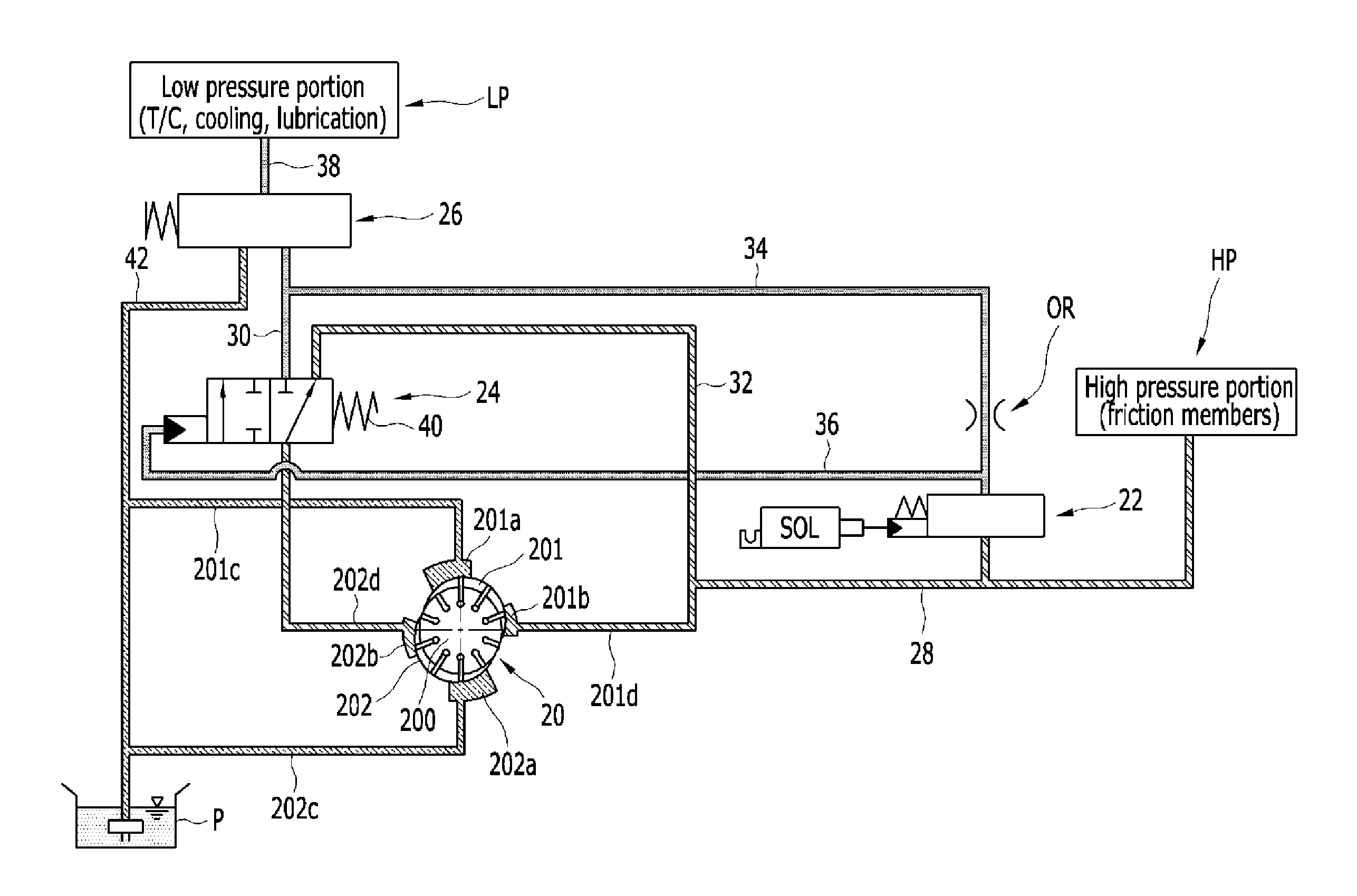
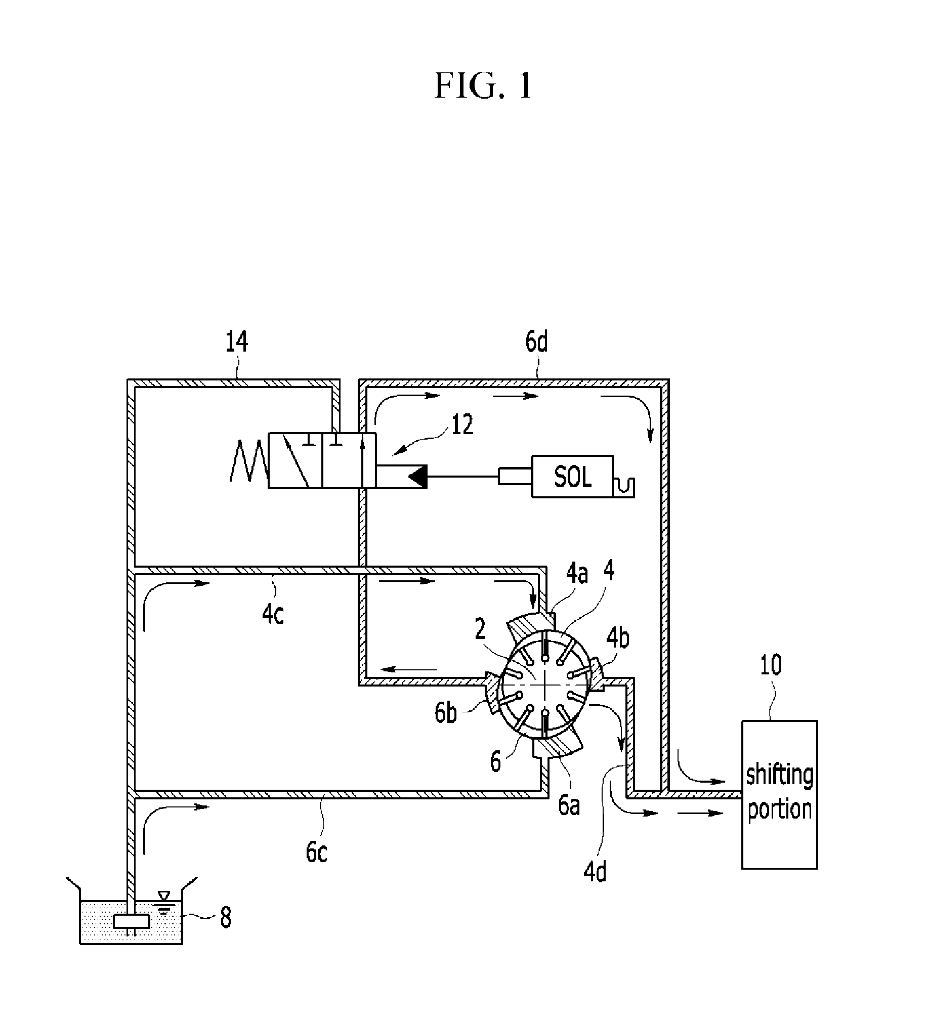
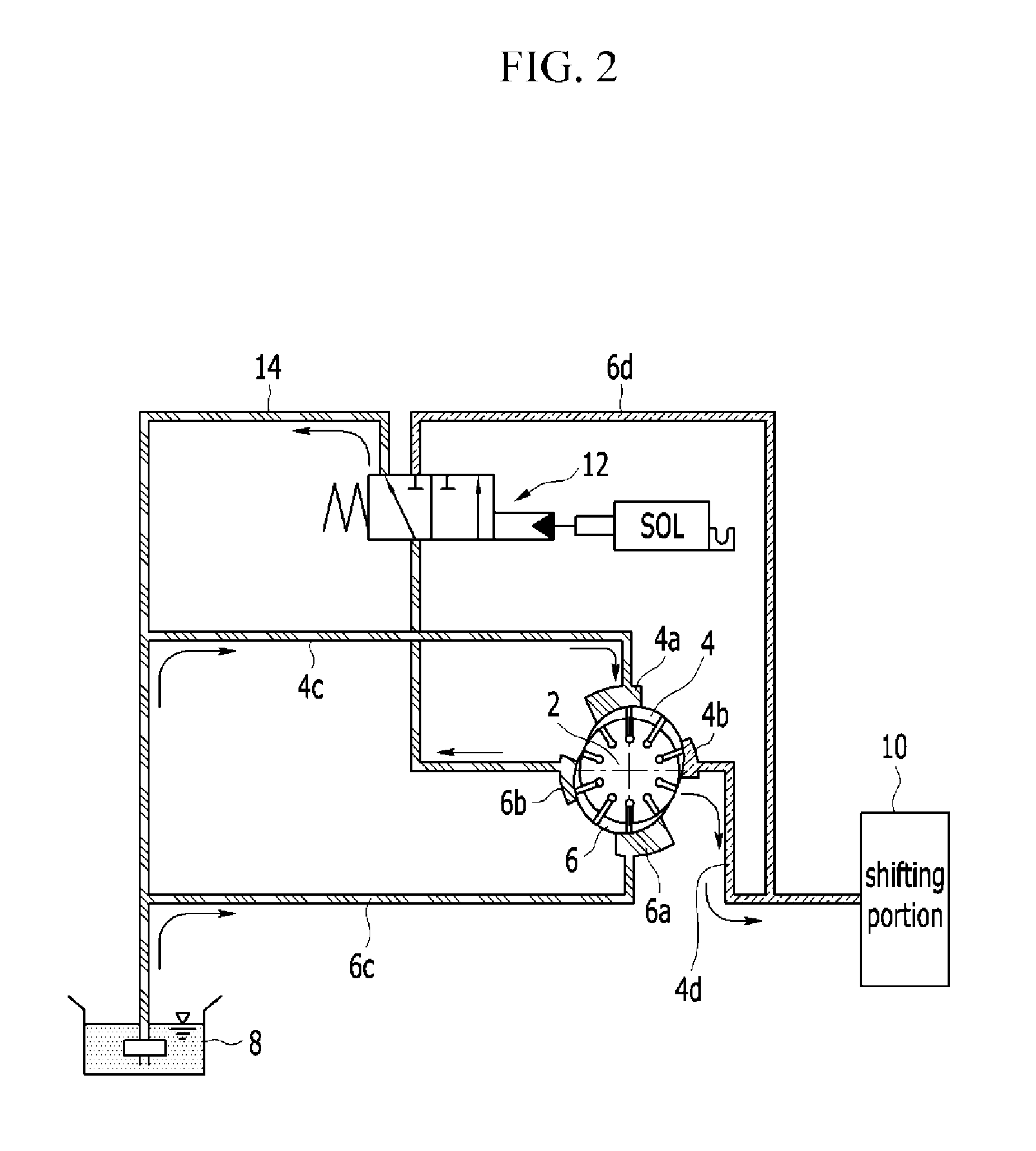
This patent is about a hydraulic pressure supply system for an automatic transmission in a vehicle. The system has the advantage of increasing the amount of oil in the lower pressure portion by supplying recirculated hydraulic pressure to it at a half discharge mode. This improves fuel economy by reducing the speed at which the half discharge mode enters.

Problems solved by technology

If the vane pump is controlled to supply the sufficient oil at the low speed region, unnecessarily much oil is supplied and thereby causes driving loss of the pump at a high speed region.

Method used


Image

  • Hydraulic pressure supply system of automatic transmission for vehicle
  • Hydraulic pressure supply system of automatic transmission for vehicle
  • Hydraulic pressure supply system of automatic transmission for vehicle

Examples


Embodiment Construction

[0058]Reference will now be made in detail to various embodiments of the present invention(s), examples of which are illustrated in the accompanying drawings and described below. While the invention(s) will be described in conjunction with exemplary embodiments, it will be understood that present description is not intended to limit the invention(s) to those exemplary embodiments. On the contrary, the invention(s) is / are intended to cover not only the exemplary embodiments, but also various alternatives, modifications, equivalents and other embodiments, which may be included within the spirit and scope of the invention as defined by the appended claims.

[0059]Description of components that are not necessary for explaining the various embodiments will be omitted, and the same constituent elements are denoted by the same reference numerals in this specification.

[0060]In the detailed description, ordinal numbers are used for distinguishing constituent elements having the same terms, and...


PUM


Abstract

A hydraulic pressure supply system of an automatic transmission for a vehicle may be provided with first and second pump chambers and may supply hydraulic pressure generated at the first and second pump chambers selectively to a high pressure portion or the high pressure portion and a low pressure portion. The hydraulic pressure generated at the first pump chamber may be supplied to the high pressure portion through a high-pressure regulator valve, and the hydraulic pressure generated at the second pump chamber may be supplied to the low pressure portion through a low-pressure regulator valve or may be supplied to the high-pressure regulator valve according to switching operation of a switch valve.

Description

CROSS-REFERENCE TO RELATED APPLICATION[0001]The present application claims priority of Korean Patent Application Number 10-2013-0089489 filed Jul. 29, 2013, the entire contents of which application is incorporated herein for all purposes by this reference.BACKGROUND OF INVENTION[0002]1. Field of Invention[0003]The present invention relates to a hydraulic pressure supply system of an automatic transmission for a vehicle. More particularly, the present invention relates to a hydraulic pressure supply system of an automatic transmission for a vehicle which increases oil amount of a low pressure portion by supplying recirculated hydraulic pressure to the low pressure portion at a half discharge mode and improves fuel economy by reducing hydraulic pressure of the low pressure portion according to hydraulic pressure of a high pressure portion and lowering rotation speed for entering the half discharge mode.[0004]2. Description of Related Art[0005]A gear pump is mainly used as a hydraulic ...

Claims


Application Information

Patent Timeline
Patent Type & Authority Applications(United States)
IPC IPC(8): F16H61/4017
CPCF16H61/4017F04C2/3446F04C2270/185F16H61/0025F16H2061/0037F16H57/04F16H61/4008F16H61/4043F16H61/431
Inventor WI, TAEHWAN
Owner HYUNDAI MOTOR CO LTD
Learn More