Ocean buoyancy power generating system

a power generation system and buoyancy technology, applied in the direction of fluid couplings, rotary clutches, couplings, etc., can solve the problems of power generators not being able to drive, air chambers immediately and drastically descend, and environmental damage, so as to achieve zero greenhouse gas, improve drawbacks and issues of conventional techniques

Inactive Publication Date: 2015-02-05
HSU KUO HUA
View PDF0 Cites 14 Cited by
  • Summary
  • Abstract
  • Description
  • Claims
  • Application Information

AI Technical Summary

Benefits of technology

[0006]The primary object of the present invention is to improve drawbacks and issues of conventional techniques. The present invention does not consume any fuels or generate wastes, air pollution, water pollution and noise pollution, and discharges nearly zero greenhouse gas (e.g., carbon dioxide) during the power generation process. Further, the present invention is capable of steadily generating electric power in all periods of the day. Moreover, the present invention generates a by-product that is fresh water that can be utilized.
[0016]The present invention features beneficial effects below. First of all, the ocean buoyancy power generating system of the present invention does not consume any fuels or generate wastes, air pollution, water pollution and noise pollution, and discharges nearly zero greenhouse gas (e.g., carbon dioxide) during the power generating process. Secondly, the ocean buoyancy power generating system of the present invention is capable of steadily generating electric power in all periods of the day. Thirdly, the ocean buoyancy power generating system of the present invention is mobile, and is thus not only extremely suitable for operations on various sea zones without any limitations, but is also free from operation complications caused by climate changes. In addition, in a preferred storage method for electric energy generated by the ocean buoyancy power generating system of the present invention, electric energy is processed by a water-electrolyzing hydrogen producing apparatus to produce hydrogen, which is the pressurized into a liquid, stored in a jar, transported to the land and converted to electric energy for further use. Further, the deep seawater obtained by the ocean buoyancy power generating system of the present invention may be treated by a desalination process. A by-product of the desalination is fresh water, which contains rich minerals and minor elements, and offers high economical values.

Problems solved by technology

However, in water storage with a dam, erosions caused by water currents below the dam are likely aggravated to lead to ecological damages.
Further, in places where the amount of rainfall vastly varies, it is frequent that power generators cannot be driven due to water shortage in the event of draughts.
However, the air chambers immediately and drastically descend when having been transported to the top by the belt.
As such, the belt may come to a temporary halt that causes interrupted electric power conversion.
Under such interrupted electric power conversion, a power storage device or a power supply system may become unstable or even damaged.
Thus, a larger space is needed for the buoyancy part to regard the rotating shaft as an axis and to rotate by utilizing the linkage gear as a support arm, resulting in increased costs.
During back-and-forth rotations with the buoyancy part, the gas output valves are constantly bent to become liable to damages.
Thus, the gas may be leaked or even the outputting process of the gas to the buoyancy part may be failed.
In severe situations, the buoyancy part may fail to float, and displacements of the buoyancy part can no longer be employed to drive the rotating shaft to further drive the power generation device to generate electric power.

Method used


Image

  • Ocean buoyancy power generating system
  • Ocean buoyancy power generating system
  • Ocean buoyancy power generating system

Examples


Embodiment Construction

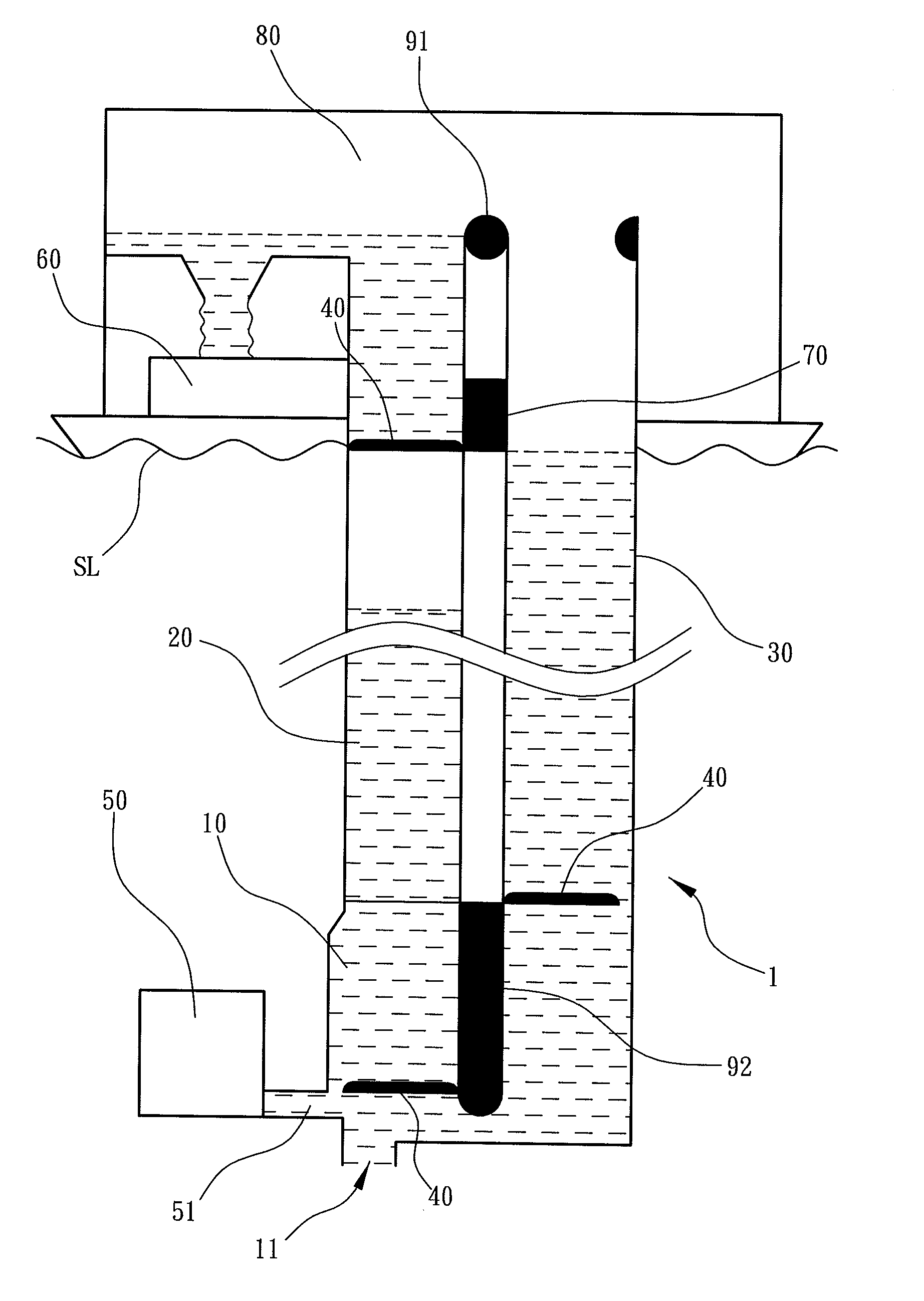
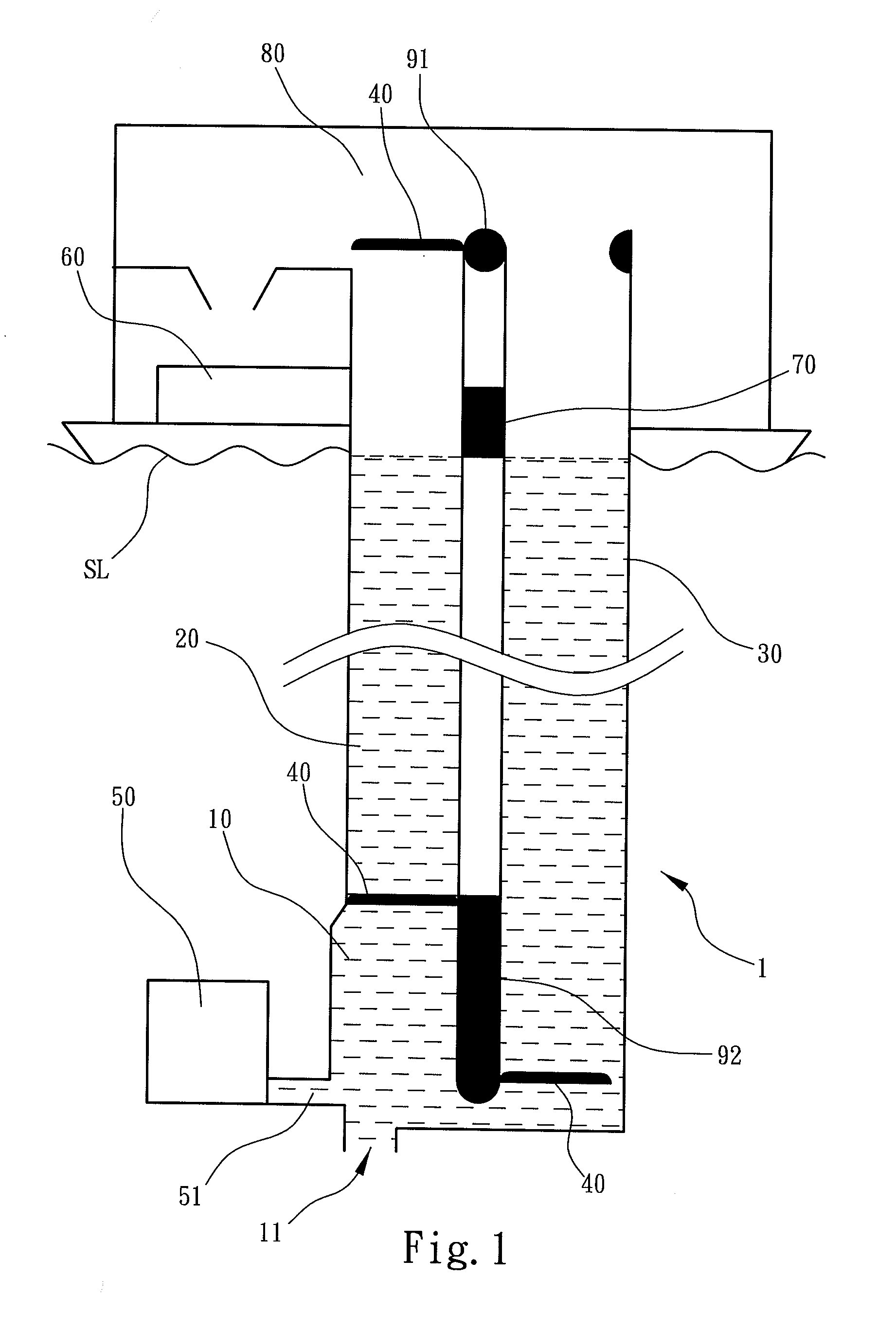
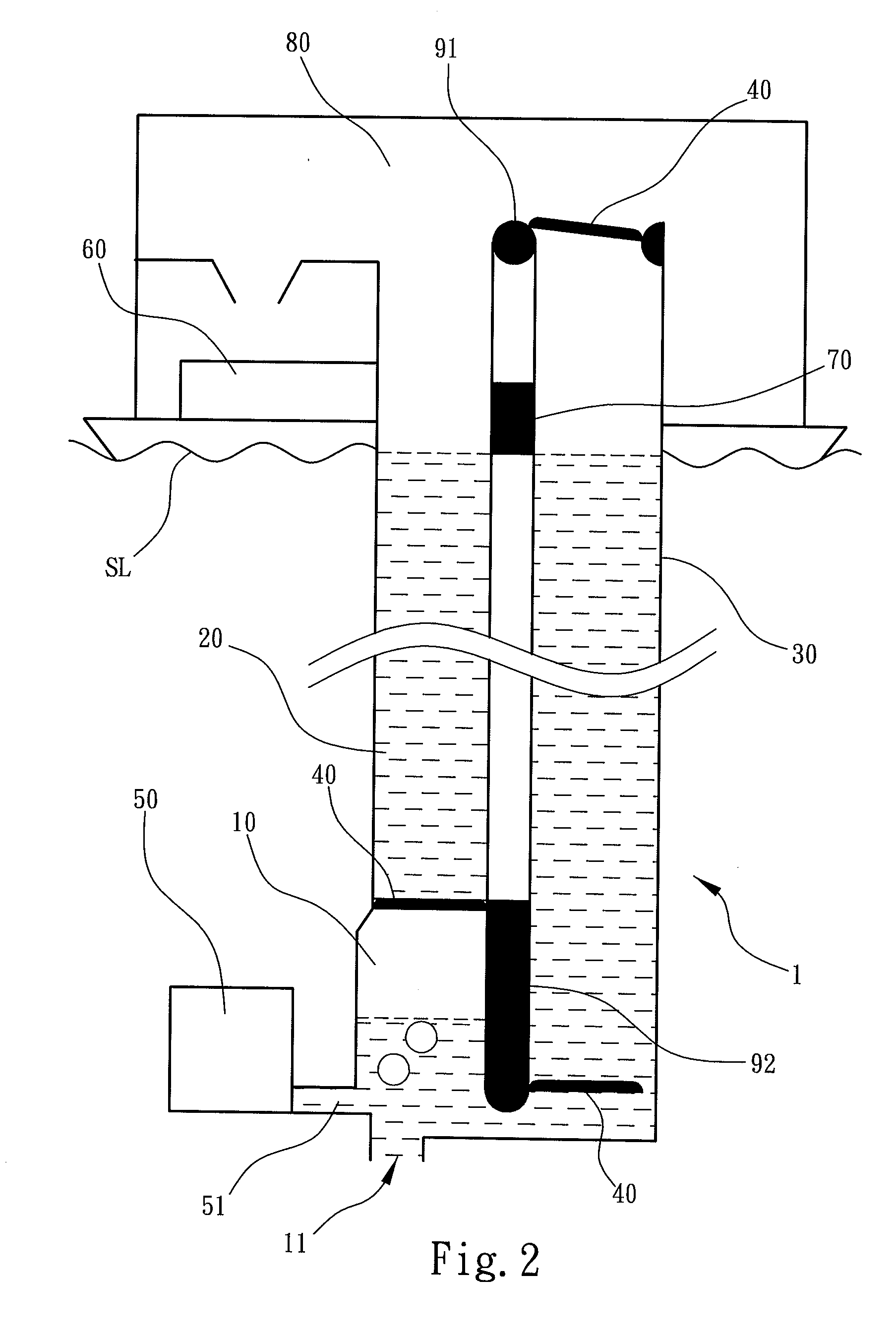
[0020]FIG. 1 shows a side view of a system according to a preferred embodiment of the present invention. To prevent from affecting denotations of symbols and lines, a seawater section line below a sea level SL and outside the present invention is omitted. As shown, a ocean buoyancy power generating system 1 of the present invention includes a water inlet pipe 10, a water drawing pipe 20, a guiding pipe 30, a plurality of water drawing devices 40 and a gas charging unit 50. The water inlet pipe 10 locates at ocean that is at least 500 meters below a sea level SL and includes a water inlet 11. The water drawing pipe 20 is connected to the water inlet pipe 10, and vertically extends out to above the sea level SL. The water inlet pipe 10 and the water drawing pipe 20 are tubes and structurally in communication with each other. Further, the water inlet pipe 10 is located in the ocean, and is connected to the water drawing pipe 20 that then vertically extends out to above the sea level SL...


PUM


Abstract

A ocean buoyancy power generating system includes a water inlet pipe with a water inlet, a water drawing pipe, a guiding pipe, multiple water drawing devices, a gas charging unit, an ocean power generating and collecting apparatus or ocean thermal energy conversion (OTEC) power generating and collecting apparatus, a first moving apparatus, and a second moving apparatus. Through cyclically discharging the gas to one of the water drawing devices in the water inlet pipe by the gas charging unit, buoyancy is generated on the water drawing device to continuously drive the seawater in the water drawing pipe to move upwards for electric power generation.

Description

FIELD OF THE INVENTION[0001]The present invention relates to a buoyancy power generating system, and particularly to a power generating system that brings deep ocean water to above the sea level by buoyancy to generate electric power.BACKGROUND OF THE INVENTION[0002]Current hydroelectric power generating systems are commonly applied in large scale power stations such as power plants and dams. A difference in water levels is usually implemented in collaboration with rotating water wheels to generate mechanical energy, which is then converted to electric energy by a power generator. However, in water storage with a dam, erosions caused by water currents below the dam are likely aggravated to lead to ecological damages. Further, in places where the amount of rainfall vastly varies, it is frequent that power generators cannot be driven due to water shortage in the event of draughts.[0003]In view of the above issues, the Taiwan Patent No. 500874 discloses a method of electrical generatio...

Claims


Application Information

Patent Timeline
Patent Type & Authority Applications(United States)
IPC IPC(8): F03B17/06
CPCF03B17/06F03B17/02F03G7/05Y02B10/50Y02E10/20Y02E10/30
Inventor HSU, KUO-HUA
Owner HSU KUO HUA
Why Eureka
Try Eureka