Ocean thermal energy conversion system and condenser thereof

a technology of thermal energy conversion and condenser, which is applied in sea energy generation, mechanical equipment, machines/engines, etc., can solve the problems of large diameter of sea water pipes for the conventional power generation system, and low actual thermal efficiency of a conventional otec plant. achieve the effect of small pipe diameter

Active Publication Date: 2013-04-23
IND TECH RES INST
View PDF10 Cites 11 Cited by
  • Summary
  • Abstract
  • Description
  • Claims
  • Application Information

AI Technical Summary

Benefits of technology

[0010]Accordingly, the present invention of an ocean thermal energy conversion (OTEC) system is to dispose a condenser underwater which would solve the problems in the prior art that a sea water pipe of a conventional OTEC system is easily damaged due to harsh operating environment.

Problems solved by technology

Moreover, since constitutional elements of a power generation system all have pressure loss and heat dissipation, the actual thermal efficiency of a conventional OTEC plant is only 2.0-3.0%.
Since the actual thermal efficiency of a conventional OTEC plant is low, the plant requires both a large amount of surface sea water and deep sea water in the conventional art to meet the demand for the rated power capacity of the plant.
Since the large amount of sea water requirement, the diameter of a sea water pipe for the conventional power generation system is quite huge.
While using such a sea water pipe to transport deep sea water from 700-1000 meters depth to a land-based plant, this sea water pipe encounters severe challenges such as bending stress, shear force, vibration, and warping due to the violent wave or marine current, and it is susceptibly damaged or destroyed.
Based on the above, in a conventional OTEC plant, the sea water pipe for transporting deep sea water has a high manufacturing cost (account for about 20% of the manufacturing cost of the power plant), and has a poor reliability during operation.

Method used


Image

  • Ocean thermal energy conversion system and condenser thereof
  • Ocean thermal energy conversion system and condenser thereof
  • Ocean thermal energy conversion system and condenser thereof

Examples


Embodiment Construction

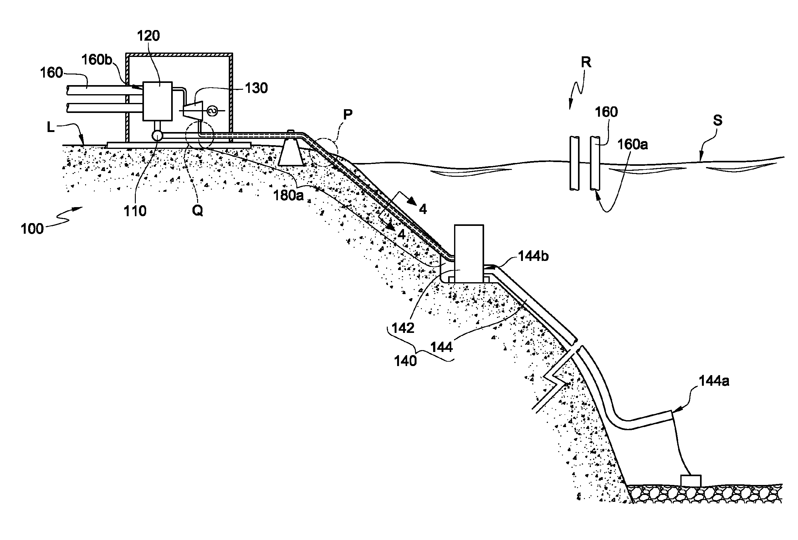
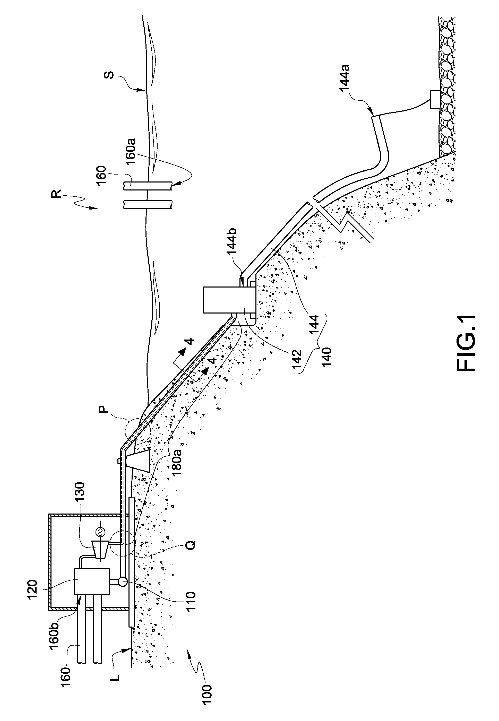
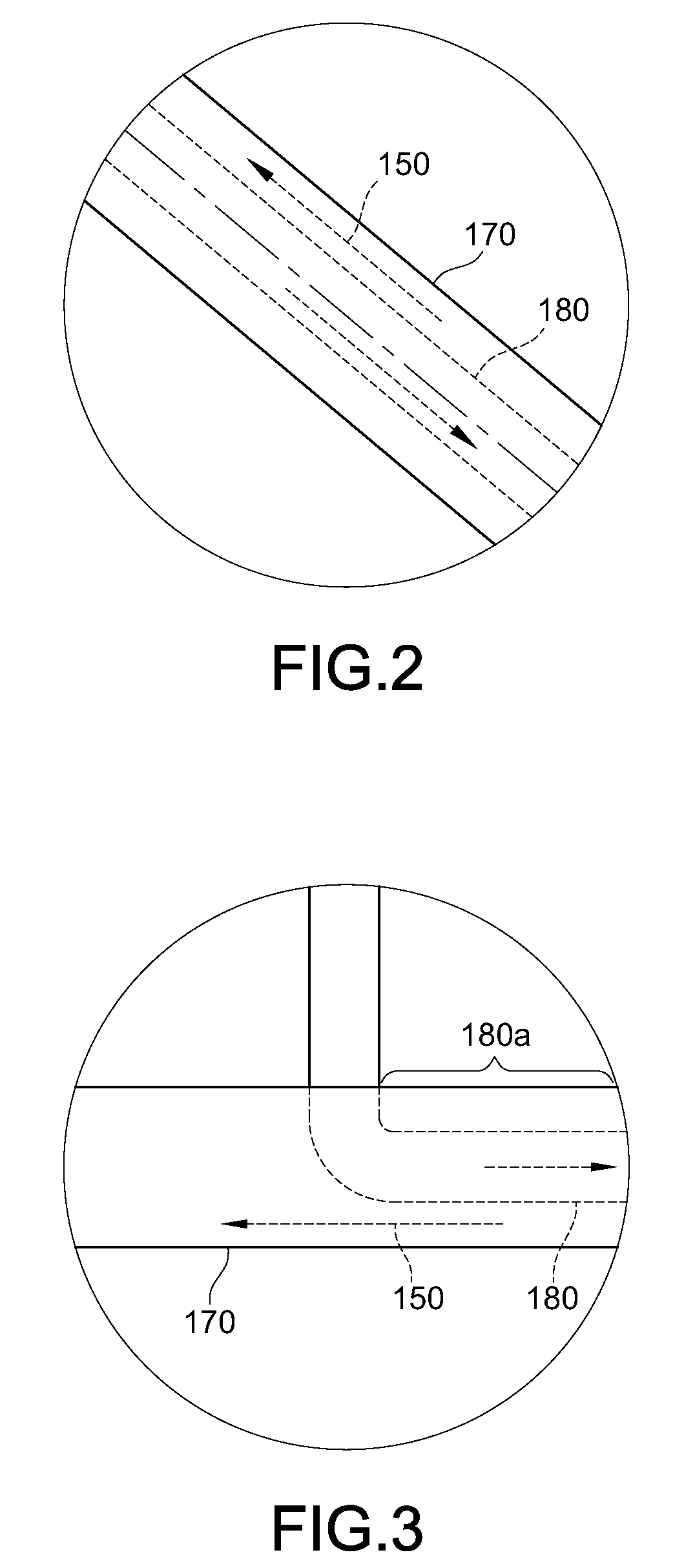
[0021]FIG. 1 is a schematic view of an ocean thermal energy conversion (OTEC) system applied in an OTEC according to an embodiment of the present invention. FIG. 2 is a schematic enlarged view of a region P in FIG. 1. FIG. 3 is a schematic enlarged view of a region Q in FIG. 1. Referring to FIGS. 1 to 3 together, the OTEC system 100 includes a working fluid pump 110, an evaporator 120, a turbine 130, a condenser 140, and some kind of working fluid 150. The working fluid 150 is, for example, ammonia (R717), carbon dioxide (R744), refrigerant (such as R134a), or other kind of working fluid with a low boiling point. For convenient illustration, this embodiment takes ammonia (R717) as an example of the working fluid 150 for illustration.

[0022]The evaporator 120 owns working fluid side and water side. At the working fluid side, its inlet is connected to the outlet of the working fluid pump 110; and its outlet is connected to the inlet of the turbine 130. At the water side, surface sea wa...


PUM


Abstract

An ocean thermal energy conversion (OTEC) system includes a working fluid pump, an evaporator, a turbine, a condenser, and a working fluid. The evaporator is connected to the working fluid pump. The turbine is connected to the evaporator. The condenser is respectively connected to the turbine and the working fluid pump, and located in a sea area below sea surface. The condenser includes a condenser main body and a deep sea water pipe. The condenser main body is respectively connected to the turbine and the working fluid pump. The deep sea water pipe is connected to the condenser main body, and has an inlet end and an outlet end. The deep sea water pipe is connected to the condenser main body via the outlet end. The working fluid flows between the working fluid pump, the evaporator, the turbine, and the condenser under the driven of the working fluid pump.

Description

CROSS-REFERENCE TO RELATED APPLICATIONS[0001]This non-provisional application claims priority under 35 U.S.C. §119(a) on Patent Application No(s). 097144211 filed in Taiwan, R.O.C. on Nov. 14, 2008 the entire contents of which are hereby incorporated by reference.BACKGROUND OF THE INVENTION[0002]1. Field of Invention[0003]The present invention relates to a power generation system and a condenser thereof, and more particularly to an ocean thermal energy conversion (OTEC) system and a condenser thereof.[0004]2. Related Art[0005]With the rapid consumption of crude oil reserves in the world, renewable energies such as solar energy, wind, geothermal, ocean energy, and biomass energy having advantages such as cleanness, permanence, low carbon content, and low pollution, have gradually received worldwide attention. Among these, a closed type ocean thermal energy conversion (OTEC) plant employs Rankine cycle power system to convert the temperature thermal energy (a temperature difference) b...

Claims


Application Information

Patent Timeline
Patent Type & Authority Patents(United States)
IPC IPC(8): F03G7/05
CPCF03G7/05Y02E10/34Y02E10/30
Inventor HSU, PO-HUAKUO, CHI-JUNG
Owner IND TECH RES INST
Why Eureka
Try Eureka