Sealed Gimbal for Ocean Thermal Energy Conversion Cold Water Pipe

a cold water pipe and seal technology, applied in the field of floating vessels, can solve the problems of large diameter seals with high differential pressure at presen

Active Publication Date: 2014-03-06
SINGLE BUOY MOORINGS INC
View PDF17 Cites 11 Cited by
  • Summary
  • Abstract
  • Description
  • Claims
  • Application Information

AI Technical Summary

Problems solved by technology

As the OTEC concept has thus far only been demonstrated in small, prototype operations, large diameter gimbal seals with high differential pressures are unknown at present.

Method used


Image

  • Sealed Gimbal for Ocean Thermal Energy Conversion Cold Water Pipe
  • Sealed Gimbal for Ocean Thermal Energy Conversion Cold Water Pipe
  • Sealed Gimbal for Ocean Thermal Energy Conversion Cold Water Pipe

Examples


Embodiment Construction

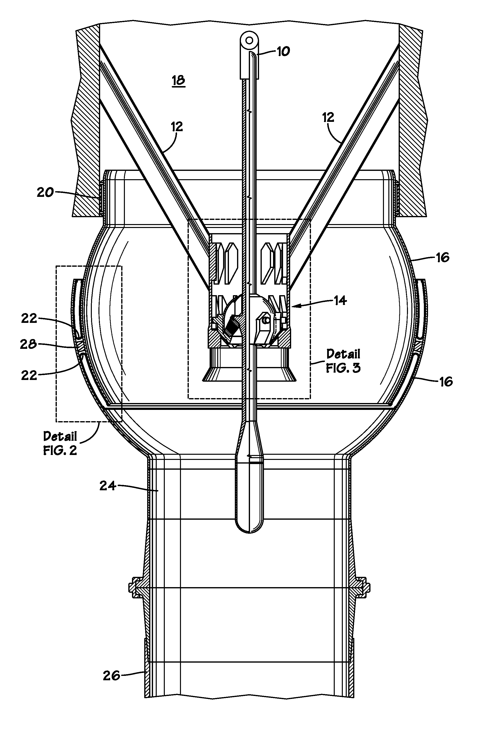
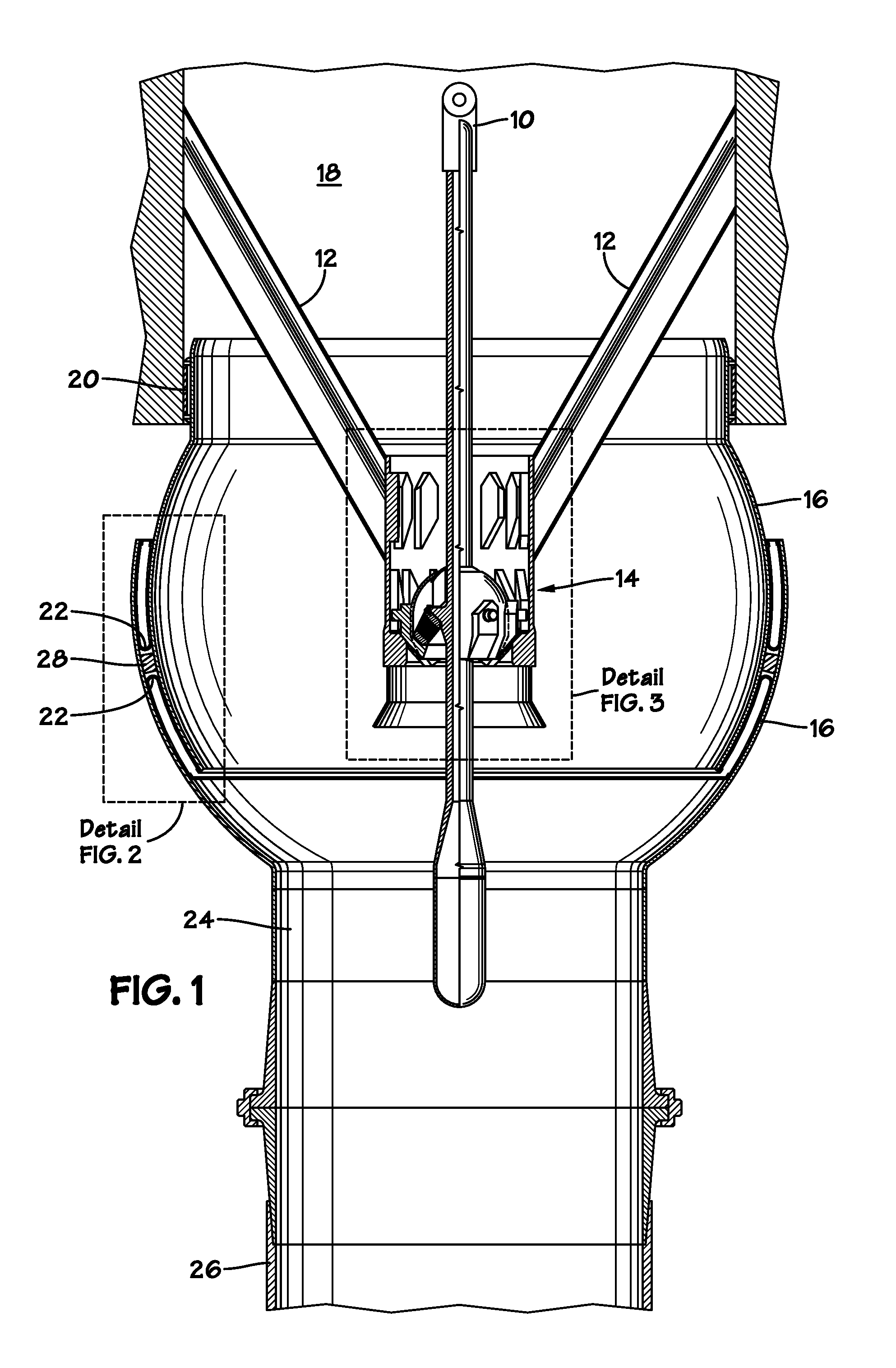
[0017]The invention may best be understood by reference to the exemplary embodiment(s) illustrated in the drawing figures.

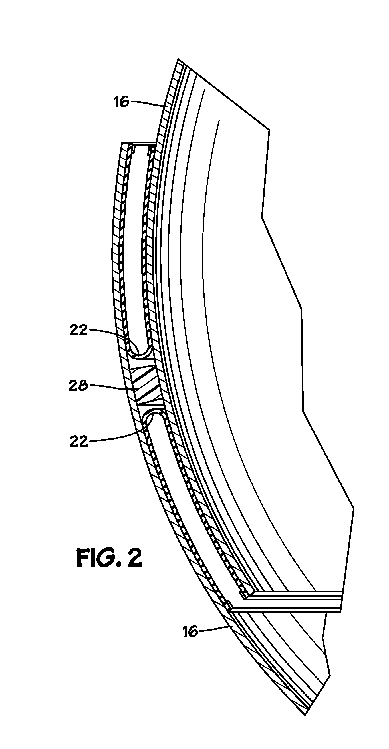
[0018]The structural connection consists of a centrally-located passive rotating latch and spherical elastomeric flexible joint which may be capable of angles of + / −20 degrees under axial loading of approximately 500 tonnes. The outer gimbal seal consists of overlapping spherical shells sealed by rolling diaphragms with opposing concave surfaces to the positive pressure differentials. The spherical shells are overlapped and nested as to rotate about the flexible joint while maintaining a constant sealing gap of minimal pressure area. The rolling diaphragm seals provide effective sealing at large sealing interface excursions without friction due to rubbing or sliding.

[0019]The rolling diaphragm seal “bending front” does not stay in one place with respect to the outer shell. The sealing front shifts by the percent difference of the two radii times the sealing arc d...


PUM

PropertyMeasurementUnit
angleaaaaaaaaaa
depthsaaaaaaaaaa
diameteraaaaaaaaaa

Abstract

A gimbal that provides for passive vertical latching and unlatching of a Cold Water Pipe (CWP) in a floating vessel such as an Ocean Thermal Energy Conversion (OTEC) facility is sealingly connected to a cold water sump on the floating vessel. The CWP gimbal is capable of reacting all static and dynamic forces of the suspended CWP at angles on the order of + / −20 degrees while remaining sealed at high differential pressures.

Description

CROSS-REFERENCE TO RELATED APPLICATIONS[0001]This application claims the benefit of U.S. Provisional Application No. 61 / 695,880, filed on Aug. 31, 2012.STATEMENT REGARDING FEDERALLY SPONSORED RESEARCH OR DEVELOPMENT[0002]Not ApplicableBACKGROUND OF THE INVENTION[0003]1. Field of the Invention[0004]This invention relates to floating vessels requiring the input of large volumes of cold seawater to support onboard processes—e.g., Ocean Thermal Energy Conversion (OTEC) facilities, floating natural gas liquefaction plantships, and the like. More particularly, it relates to the Cold Water Pipe (CWP) used to bring cold water up from depth in such facilities.[0005]2. Description of the Related Art Including Information Disclosed Under 37 CFR 1.97 and 1.98[0006]The OTEC (Ocean Thermal Energy Conversion) process uses the temperature difference between warm surface seawater and cold, deep seawater (˜1000 m below the surface) to power a heat engine and produce useful work, usually in the form o...

Claims


Application Information

Patent Timeline
Patent Type & Authority Applications(United States)
IPC IPC(8): F16L3/00
CPCF16L3/00F03G7/05F16L27/04Y02E10/34Y10T29/49815Y10T29/49826F16L27/103Y02E10/30E21B17/01E21B19/004
Inventor RIGGS, DAVID, C.
Owner SINGLE BUOY MOORINGS INC
Why Eureka
Try Eureka