System and method of controlling combustion and emissions in gas turbine engine with exhaust gas recirculation

a technology of exhaust gas recirculation and combustion control, which is applied in the direction of machines/engines, combustion types, lighting and heating apparatus, etc., can solve the problems of increasing the concentration of oxidant in the exhaust gas, reducing the life of the components,

Active Publication Date: 2015-02-05
GENERAL ELECTRIC CO +1
View PDF51 Cites 40 Cited by
  • Summary
  • Abstract
  • Description
  • Claims
  • Application Information

AI Technical Summary

Problems solved by technology

Unfortunately, certain components of the combustor section are exposed to high temperatures, which may reduce the life of the components.
Furthermore, cooling the components or combustion gases with oxidant may increase the concentrations of oxidant in the exhaust gas.

Method used


Image

  • System and method of controlling combustion and emissions in gas turbine engine with exhaust gas recirculation
  • System and method of controlling combustion and emissions in gas turbine engine with exhaust gas recirculation
  • System and method of controlling combustion and emissions in gas turbine engine with exhaust gas recirculation

Examples


embodiment 1

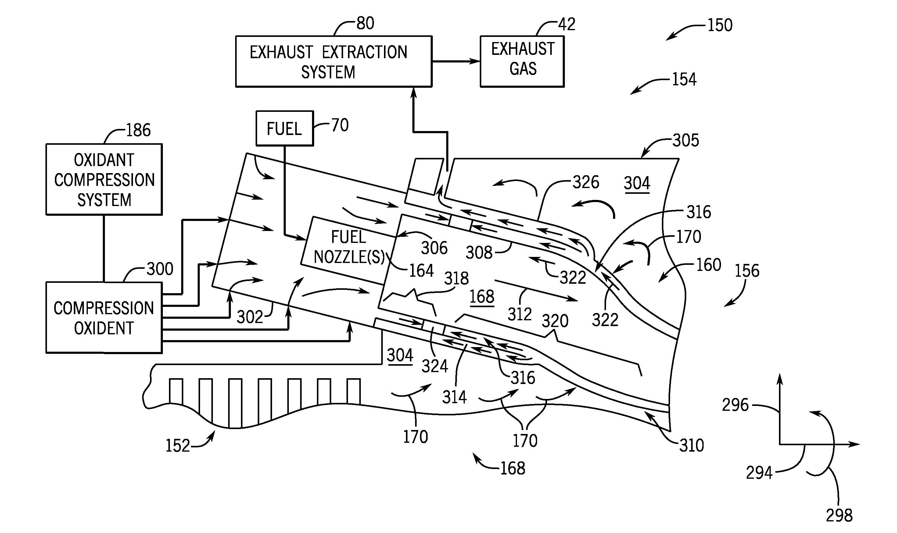
[0091]A system having a turbine combustor with a combustor liner disposed about a combustion chamber and a head end upstream of the combustion chamber relative to a downstream direction of a flow of combustion gases through the combustion chamber. The head end is configured to direct an oxidant flow and a first fuel flow toward the combustion chamber. The turbine combustor also includes a flow sleeve disposed at an offset about the combustor liner to define a passage configured to direct a gas flow toward the head end and configured to direct a portion of the oxidant flow toward a turbine end of the turbine combustor. The gas flow includes a substantially inert gas. The turbine combustor also includes a barrier within the passage, and the barrier is configured to block the portion of the oxidant flow toward the turbine end and to is configured to block the gas flow toward the head end within the passage

embodiment 2

[0092]The system of embodiment 1, wherein the oxidant flow and the first fuel flow are configured to substantially stoichiometrically combust in the combustion chamber.

embodiment 3

[0093]The system of any preceding embodiment, wherein the head end includes a first fuel nozzle configured to direct the first fuel flow into the combustion chamber, and a second fuel nozzle configured to direct a second fuel flow into the combustion chamber, wherein the first fuel nozzle is controlled separately from the second fuel nozzle.


PUM


Abstract

In one embodiment, a system includes a turbine combustor having a combustor liner disposed about a combustion chamber, a head end upstream of the combustion chamber relative to a downstream direction of a flow of combustion gases through the combustion chamber, a flow sleeve disposed at an offset about the combustor liner to define a passage, and a barrier within the passage. The head end is configured to direct an oxidant flow and a first fuel flow toward the combustion chamber. The passage is configured to direct a gas flow toward the head end and to direct a portion of the oxidant flow toward a turbine end of the turbine combustor. The gas flow includes a substantially inert gas. The barrier is configured to block the portion of the oxidant flow toward the turbine end and to block the gas flow toward the head end within the passage.

Description

CROSS-REFERENCE TO RELATED APPLICATIONS[0001]This application claims priority to and benefit of U.S. Provisional Patent Application No. 61 / 860,214, entitled “SYSTEM AND METHOD OF CONTROLLING COMBUSTION AND EMISSIONS IN GAS TURBINE ENGINE WITH EXHAUST GAS RECIRCULATION,” filed Jul. 30, 2013, which is hereby incorporated by reference in its entirety for all purposes.BACKGROUND[0002]The subject matter disclosed herein relates to gas turbines, and more specifically, to gas turbines with exhaust gas recirculation.[0003]Gas turbine engines are used in a wide variety of applications, such as power generation, aircraft, and various machinery. Gas turbine engines generally combust a fuel with an oxidant (e.g., air) in a combustor section to generate hot combustion gases, which then drive one or more turbine stages of a turbine section. In turn, the turbine section drives one or more compressor stages of a compressor section, thereby compressing oxidant for intake into the combustor section a...

Claims


Application Information

Patent Timeline
Patent Type & Authority Applications(United States)
IPC IPC(8): F23N1/02F23R3/26F23R3/16F23R3/00
CPCF23N1/02F23R3/002F23N2021/12F23R3/16F23N2041/20F23R3/26F23C9/08F23C2202/30Y02E20/16F02C3/34F02C1/005F23C9/00F23C2202/20F05D2270/083F05D2260/61F05D2270/08F23R3/40F23N2221/12F23N2241/20Y02T50/60
Inventor SLOBODYANSKIY, ILYA ALEKSANDROVICHDAVIS, JR., LEWIS BERKLEYMINTO, KARL DEAN
Owner GENERAL ELECTRIC CO
Why Eureka
Try Eureka