Touch panel

a capacitive touch panel and projective technology, applied in the field of projective capacitive touch panels, can solve the problems of etchant damage to the narrow parts of the conductive series covered by the small separated insulator, open circuit, and the likelihood of suffering from electrostatic discharge damage, etc., to achieve the effect of favorable quality and reliability

Inactive Publication Date: 2015-02-05
WINTEK CORP
View PDF3 Cites 11 Cited by
  • Summary
  • Abstract
  • Description
  • Claims
  • Application Information

AI Technical Summary

Benefits of technology

[0005]The invention is directed to a touch panel characterized by favorable quality and reliability, so as to prevent open

Problems solved by technology

Besides, if the small separated insulators are not well manufactured, e.g., if the peripheries of the small separated insulators are peeled off, the narrow parts of the conductive series covered by the small separated insu

Method used


Image

  • Touch panel
  • Touch panel
  • Touch panel

Examples


first embodiment

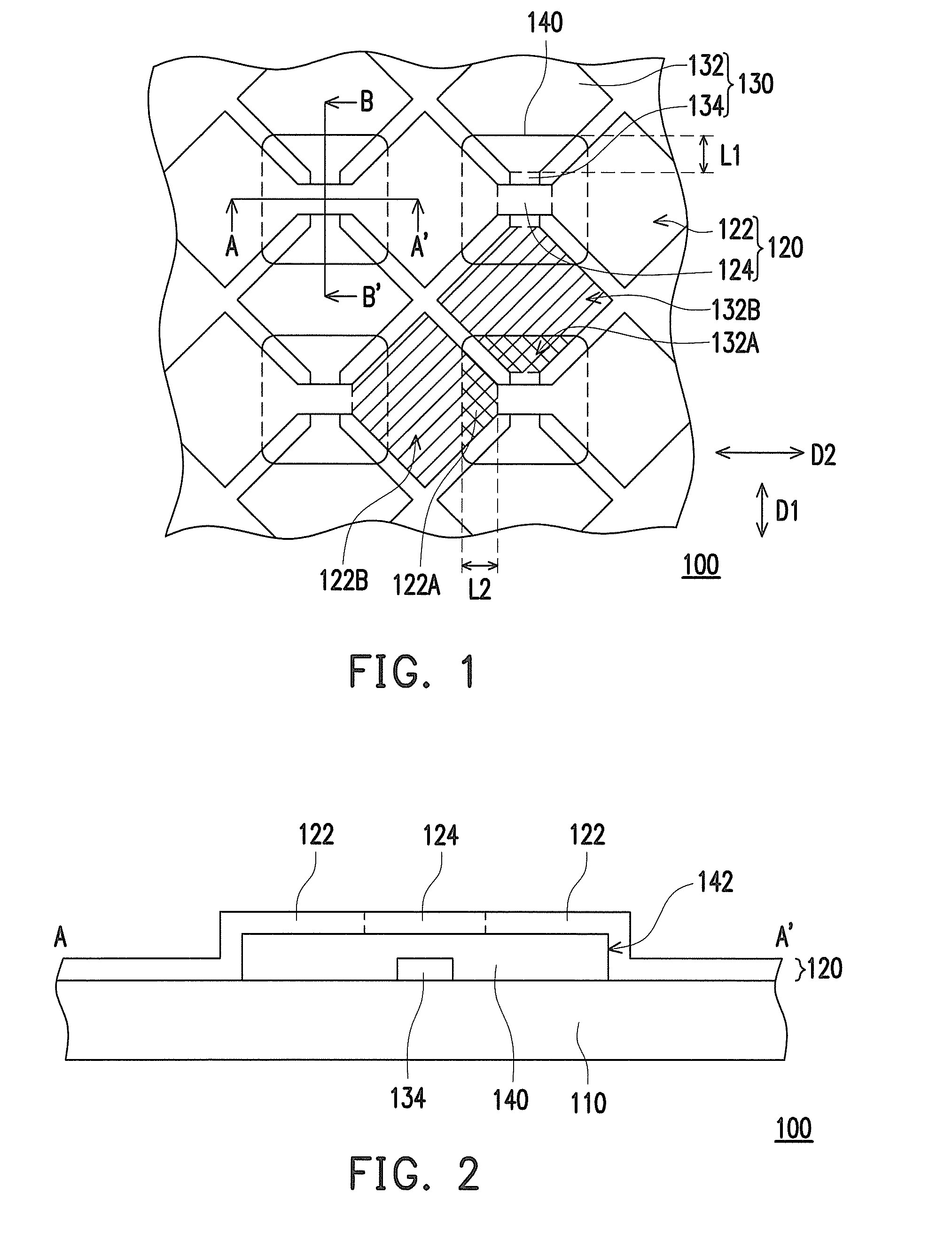
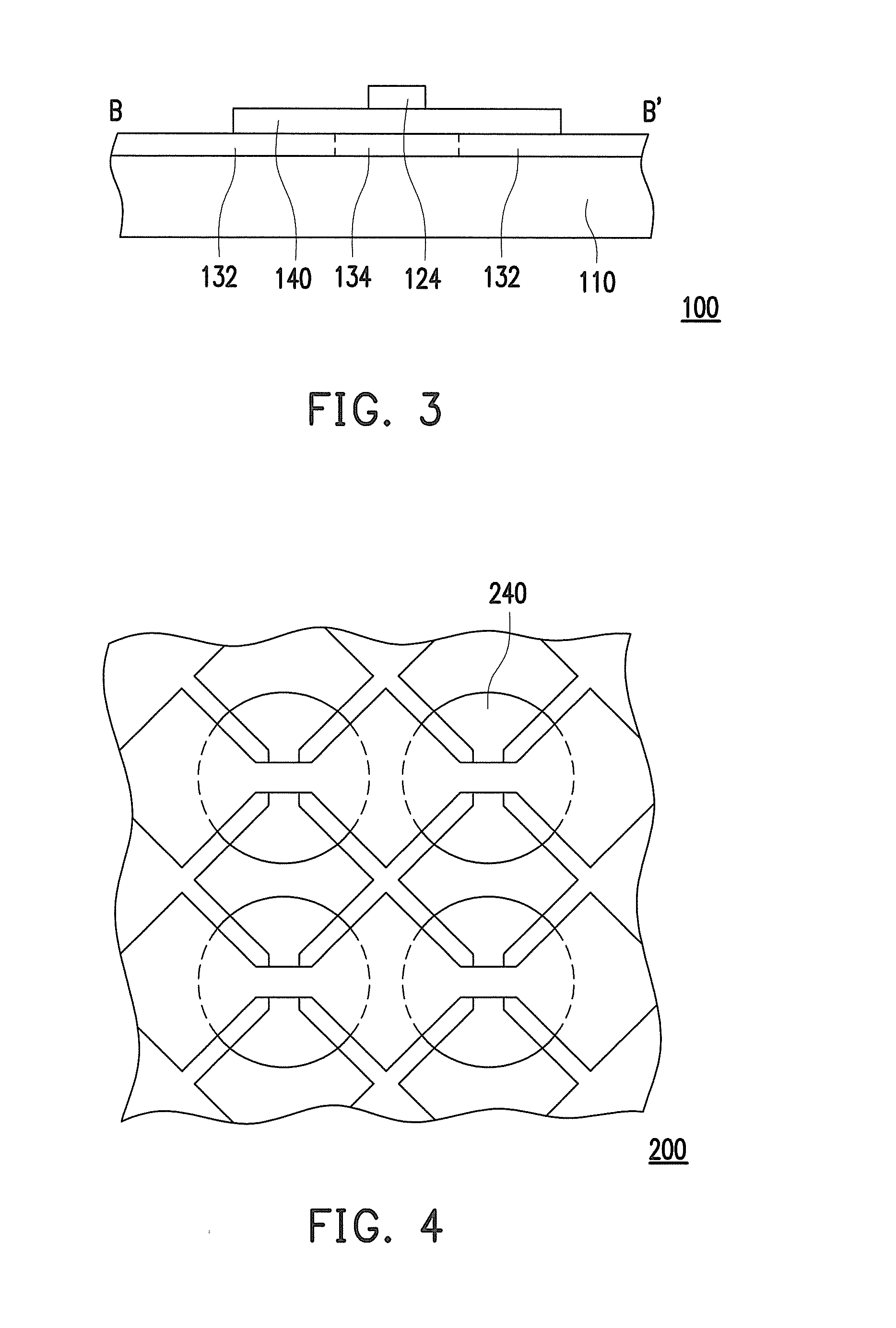
[0038]FIG. 1 is a schematic partial top view illustrating a touch panel according to the invention. FIG. 2 is a schematic cross-sectional view illustrating the touch panel depicted in FIG. 1 along a section line A-A′. FIG. 3 is a schematic cross-sectional view illustrating the touch panel depicted in FIG. 1 along a section line B-B′. With reference to FIG. 1 to FIG. 3, a touch panel 100 includes a substrate 110, a plurality of first conductive series 130, a plurality of second conductive series 120, and a plurality of insulation patterns 140. The first conductive series 130, the second conductive series 120, and the insulation patterns 140 are located on the same side of the substrate 110. The first conductive series 130 and the second conductive series 120 are intersected with each other and electrically independent by disposing the insulation patterns 140 at the intersection areas thereof. Thereby, the touch sensing functions can be performed due to the capacitive effects generate...

fourth embodiment

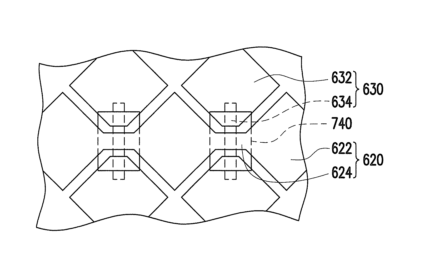
[0051]FIG. 6 is a schematic partial top view illustrating a touch panel according to the invention. FIG. 7 is a schematic cross-sectional view illustrating the touch panel depicted in FIG. 6 along a section line C-C′, and FIG. 8 is a schematic cross-sectional view illustrating the touch panel depicted in FIG. 6 along a section line D-D′. With reference to FIG. 6, FIG. 7, and FIG. 8, a touch panel 400 includes a substrate 110, a plurality of first conductive series 130, a plurality of second conductive series 420, and a plurality of insulation patterns 140. The first conductive series 130, the second conductive series 420, and the insulation patterns 140 are located on the same side of the substrate 110. The first conductive series 130 and the second conductive series 420 are intersected with each other and electrically independent by disposing the insulation patterns 140 at the intersection areas thereof. Specifically, the detailed description of the substrate 110, the first conduct...

fifth embodiment

[0055]FIG. 10 is a schematic top view of a touch panel according to the invention. With reference to FIG. 10, a touch panel 500 includes a substrate 110, a plurality of first conductive series 530, a plurality of second conductive series 420, and a plurality of insulation patterns 140. The first conductive series 530, the second conductive series 420, and the insulation patterns 140 are located on the same side of the substrate 110. The first conductive series 530 and the second conductive series 420 are intersected with each other and electrically independent by disposing the insulation patterns 140 at the intersection areas thereof. Specifically, the detailed description of the substrate 110, the second conductive series 420, and the insulation patterns 140 are described in the above embodiments and thus will not be further explained hereinafter. The first conductive series 530, however, are further elaborated below.

[0056]According to the present embodiment, each of the first cond...


PUM


Abstract

A touch panel includes a substrate, first conductive series, second conductive series, and insulation patterns. Each of the first conductive series includes first conductive patterns arranged in a first direction and first narrow portions, and each first narrow portion is connected to two adjacent first conductive patterns. The second conductive series are insulated from the first conductive series. Each of the second conductive series extends in a second direction and includes a plurality of intersections intersected with the first narrow portions. The insulation patterns are located between the first narrow portions and the intersections, so that one of the first narrow portions and a respective one of the intersections intersected with the one of the first narrow portions are separate. An edge of each of the insulation patterns and one of the first conductive patterns of each of the first conductive series partially overlap.

Description

CROSS-REFERENCE TO RELATED APPLICATION[0001]This application claims the priority benefit of Taiwan application serial no. 102214418, filed on Jul. 31, 2014. The entirety of the above-mentioned patent application is hereby incorporated by reference herein and made a part of this specification.FIELD OF THE INVENTION[0002]The invention relates to a touch apparatus; more particularly, the invention relates to a projective capacitive touch panel.DESCRIPTION OF RELATED ART[0003]With the blooming development in the electronic technology and the prevalence of wireless communication and the interne, touch panels are often employed as human-machine interfaces between human beings and smart devices to perform control functions. The well-known touch panels include resistive touch panels and capacitive touch panels, in which the capacitive touch panels became an attractive alternative to resistive and other known touch panels for a variety of reasons, including good optical properties, reliabili...

Claims


Application Information

Patent Timeline
IPC IPC(8): H03K17/96G06F3/044
CPCH03K17/9622H03K2017/9613H03K2217/960705G06F3/044G06F3/0443
Inventor LI, CHUNG-HSIENCHEN, KUO-HSINGHUANG, SIANG-LINCHEN, YU-TINGCHOU, CHIEN-LIANG
Owner WINTEK CORP
Why Eureka
Try Eureka