Grinding system and spot welding system

a technology of grinding system and spot welding, which is applied in the direction of grinding machine components, manufacturing tools, and maintenance of electric motors, can solve the problems of degrading welding accuracy and widespread use of conventional spot welders

Inactive Publication Date: 2015-02-05
YASKAWA DENKI KK
View PDF5 Cites 17 Cited by
  • Summary
  • Abstract
  • Description
  • Claims
  • Application Information

AI Technical Summary

Problems solved by technology

Conventional spot welders widely used in assembly of automobile parts or in other processing have had degraded accuracy of welding through wear of a welding tip, which is an electrode portion for clamping a workpiece, and through attachment of welding waste to the surface of the welding tip after a long period of welding processing.

Method used


Image

  • Grinding system and spot welding system
  • Grinding system and spot welding system
  • Grinding system and spot welding system

Examples


Embodiment Construction

[0019]The embodiments will now be described with reference to the accompanying drawings, wherein like reference numerals designate corresponding or identical elements throughout the various drawings.

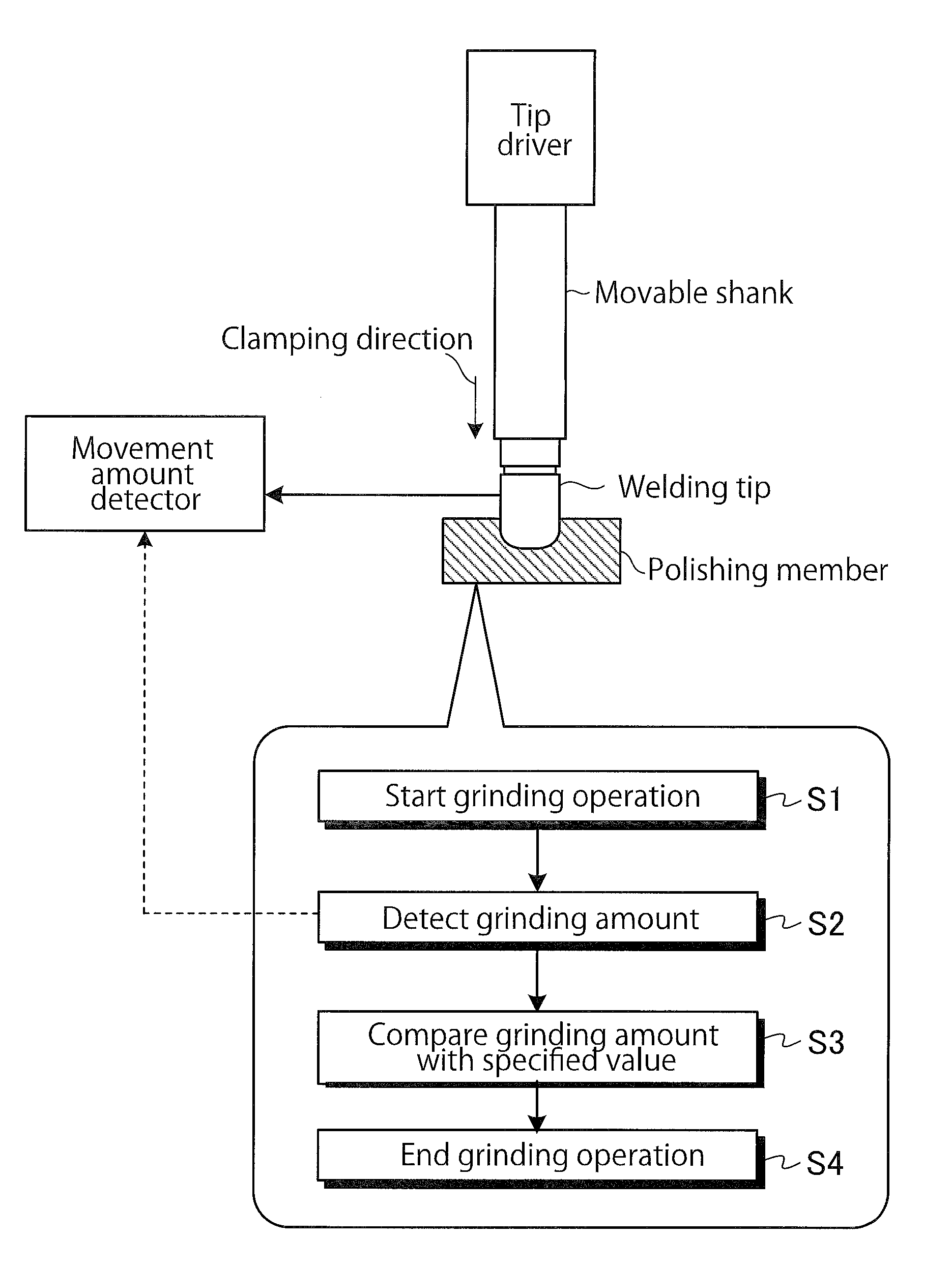
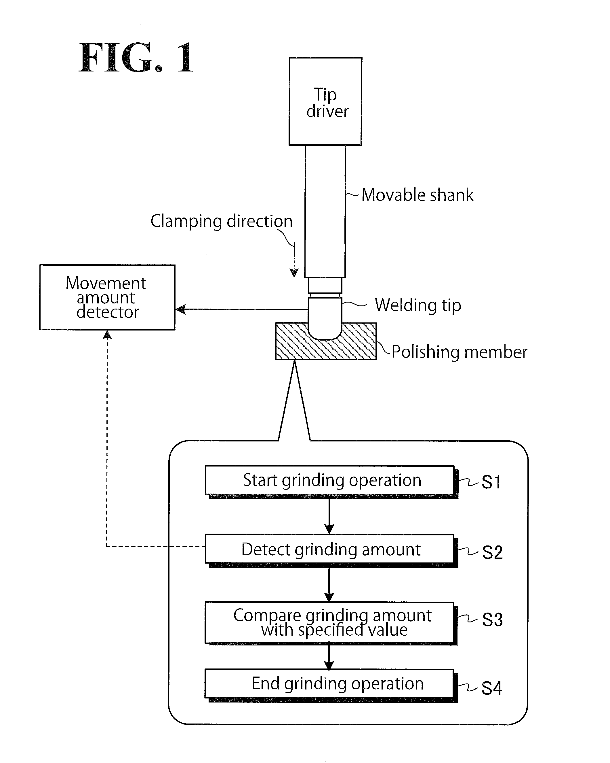
[0020]A grinding system according to this embodiment will be described by referring to FIG. 1. FIG. 1 is a diagram illustrating a procedure for a grinding operation executed by a grinding system according to this embodiment. As shown in FIG. 1, a welding tip is an electrode for resistance welding, and cooperates with another electrode, not shown, to clamp a workpiece between the electrodes and weld the workpiece. The welding tip is mounted to a distal end of a movable shank. The movable shank is movable in a clamping direction by a tip drive device.

[0021]Through increased frequency of the welding operation, the distal end of the welding tip may be subject to deformation due to heat or subject to worn, or attract welding waste, resulting in degraded welding quality. In view of this, the w...


PUM

PropertyMeasurementUnit
pressing forceaaaaaaaaaa
torqueaaaaaaaaaa
timeaaaaaaaaaa

Abstract

A grinding system includes a welding gun movable relative to a workpiece. A pair of clamp devices move relatively toward each other to clamp a workpiece. A welding tip is disposed on one of the pair of clamp devices. A detector detects a relative movement amount of the welding tip with respect to the other clamp device. A dresser grinds the welding tip. While the dresser is grinding the welding tip, a determinator determines whether to make the dresser end grinding the welding tip based on the movement amount detected by the detector. When the determinator determines to make the dresser end grinding the welding tip, an instructor instructs the dresser to end grinding the welding tip.

Description

CROSS-REFERENCE TO RELATED APPLICATIONS[0001]The present application claims priority under 35 U.S.C. §119 to Japanese Patent Application No. 2013-159632, filed Jul. 31, 2013. The contents of this application are incorporated herein by reference in their entirety.BACKGROUND[0002]1. Field of the Invention[0003]The present invention relates to a grinding system and a spot welding system.[0004]2. Discussion of the Background[0005]Conventional spot welders widely used in assembly of automobile parts or in other processing have had degraded accuracy of welding through wear of a welding tip, which is an electrode portion for clamping a workpiece, and through attachment of welding waste to the surface of the welding tip after a long period of welding processing. This has been addressed by grinding the welding tip on a regular basis using a dresser, which is a grinder, thereby keeping the surface of the welding tip at a constant level of state.[0006]To maintain a constant level of welding qu...

Claims


Application Information

Patent Timeline
Patent Type & Authority Applications(United States)
IPC IPC(8): B23K11/30B24B49/16B23K11/11
CPCB23K11/3063B24B49/16B23K11/11B23K11/115B23K11/252B24B19/00
Inventor MORI, YOSUKESONODA, TEPPEI
Owner YASKAWA DENKI KK
Why Eureka
Try Eureka