Method for operating a brake system and a brake system

a technology of brake system and brake system, which is applied in the direction of brake system, braking component, transportation and packaging, etc., can solve the problems of inability to achieve infinitely variable, comfortable and quiet pressure control with these valves, and failure of the brake circuit concerned, so as to improve the quality of control of the braking process

Active Publication Date: 2015-02-05
CONTINENTAL TEVES AG & CO OHG
View PDF12 Cites 43 Cited by
  • Summary
  • Abstract
  • Description
  • Claims
  • Application Information

AI Technical Summary

Benefits of technology

The technical effect of this patent is to improve the accuracy and efficiency of controlling brakes on vehicles with different requirements for pressure between wheels.

Problems solved by technology

The technical problem addressed in this patent relates to improving the design of brake systems for motor vehicles. Specifically, current open brake systems have limitations such as potential leaks or failures due to a lack of proper controls. Additionally, they often require expensive components like digital-controlled seats and specialized pumps. There is a need to develop a more efficient and reliable brake system that allows for better pressure control and utilizes existing technology.

Method used


Image

  • Method for operating a brake system and a brake system
  • Method for operating a brake system and a brake system
  • Method for operating a brake system and a brake system

Examples


Embodiment Construction

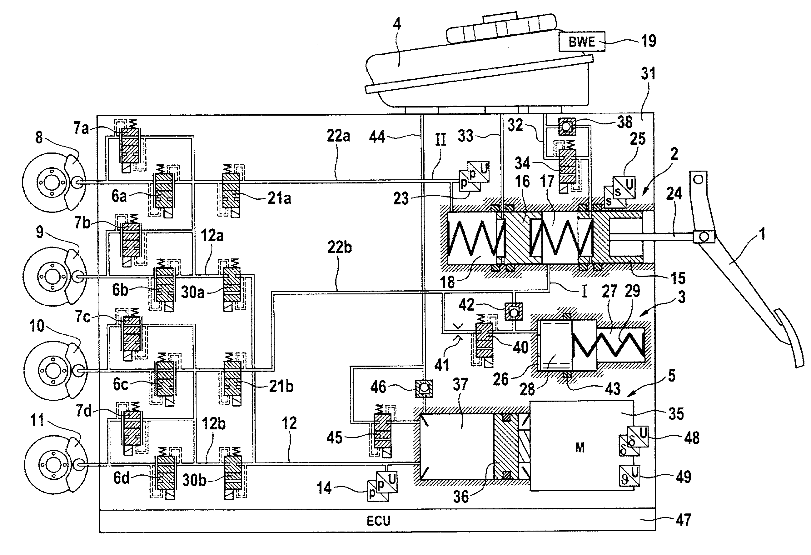
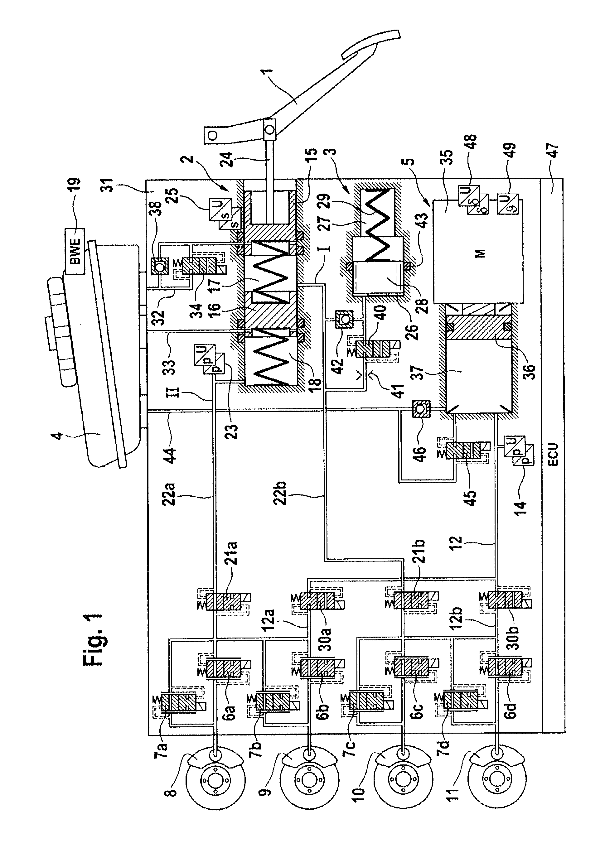
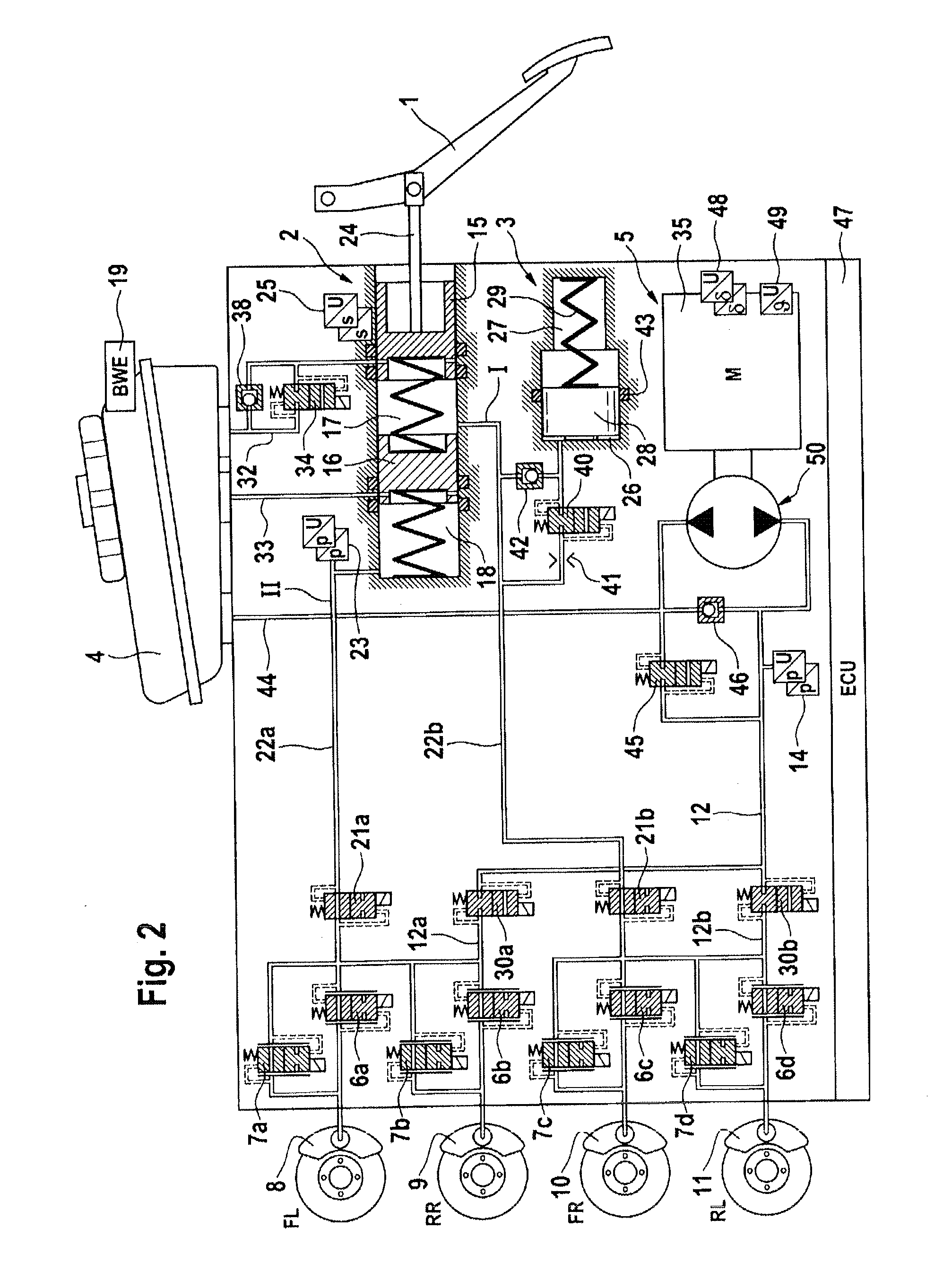
[0020]FIG. 1 shows a hydraulic circuit diagram of a brake system suitable for carrying out a method according to an aspect of the invention. The brake system illustrated consists essentially of a hydraulic actuating unit 2, which can be actuated by means of an actuating or brake pedal 1, a travel simulator 3, which interacts with the hydraulic actuating unit 2, a pressure medium reservoir 4, which is associated with the hydraulic actuating unit 2 and has an electric filling level warning device 19, an electrically controllable pressure and volume setting device 5, electrically controllable pressure modulation or inlet and outlet valves 6a-6d, 7a-7d, which are connected together hydraulically in pairs via center ports and are connected to the wheel brakes 8, 9, 10, 11 of a motor vehicle (not shown). The inlet ports of the inlet valves 6a-6d are supplied by means of system pressure lines 12a, 12b with a pressure which is designated as the system pressure. All the electrically actuable...


PUM


Abstract

A method and system for operating a motor vehicle brake system, actuated in a “Brake-by-Wire” operating mode both by the vehicle driver and also independent of the vehicle driver, preferably operated in the “Brake-by-Wire” operating mode, and which can be operated in at least one fall-back operating mode, in which only operation by the vehicle driver is possible. The brake system has an electrohydraulic pressure and volume setting device, which electronically emits a brake system pressure under control, and a pressure modulation unit having, for each wheel brake, inlet and outlet valves for setting wheel-specific brake pressures. For setting wheel-specific brake pressures, the inlet and outlet valves are actuated analogously by being energized by different electrical currents, in order to assign a pressurizing agent volume flow provided by the pressure and volume setting device to the wheel brakes that have a pressure change requirement.

Description


Claims


Application Information

Patent Timeline
Owner CONTINENTAL TEVES AG & CO OHG
Why Eureka
Try Eureka