Vehicle power source device and vehicle equipped with the power source device

a technology for power sources and vehicles, applied in electric devices, safety/protection circuits, batteries, etc., can solve the problems of power difference, switch damage, switch damage, etc., and achieve the effect of preventing the damage of the connecting switch by the rush current and small excess rush curren

Active Publication Date: 2015-02-05
SANYO ELECTRIC CO LTD
View PDF4 Cites 34 Cited by
  • Summary
  • Abstract
  • Description
  • Claims
  • Application Information

AI Technical Summary

Benefits of technology

[0025]In the above power supply device, as the control circuit equalizes voltages of the first battery and the second battery and the connecting switch 4 is turns on, even though there is a voltage difference between, at the time of turning on the connecting switch the excessive rush current can be small, and the damage of the connecting switch by the rush current can be prevented.

Problems solved by technology

As a result, a voltage difference occurs.
When there is the voltage difference between the lead battery and the lithium ion battery, the switch can be damaged by the large current caused by turning on the switch.
Especially, as the lead battery and the lithium ion battery have a low internal resistance so as to be efficiently charged by the generator, a large current flows by even the small voltage difference, and the switch can be damaged by the large current.
In contrast, as the batteries of a small capacity (Ah) tends to be over charged by a large electric power of regenerative braking, charging is restricted, or as by the battery voltage increasing a charging current becomes small, it is difficult that the electric energy outputted from the generator is efficiently stored in the batteries.

Method used


Image

  • Vehicle power source device and vehicle equipped with the power source device
  • Vehicle power source device and vehicle equipped with the power source device

Examples


Embodiment Construction

[0028]Embodiments of the present invention will be described below based on the drawings. Note, however, that the embodiments shown below exemplify a vehicle power source device and a vehicle equipped with the power supply device for embodying the technical idea of the present invention, and the present invention does not specify a vehicle power source device and a vehicle equipped with the power supply device to those shown below. In particular, it does not mean that the members shown in the claims are specified to the members in the embodiments.

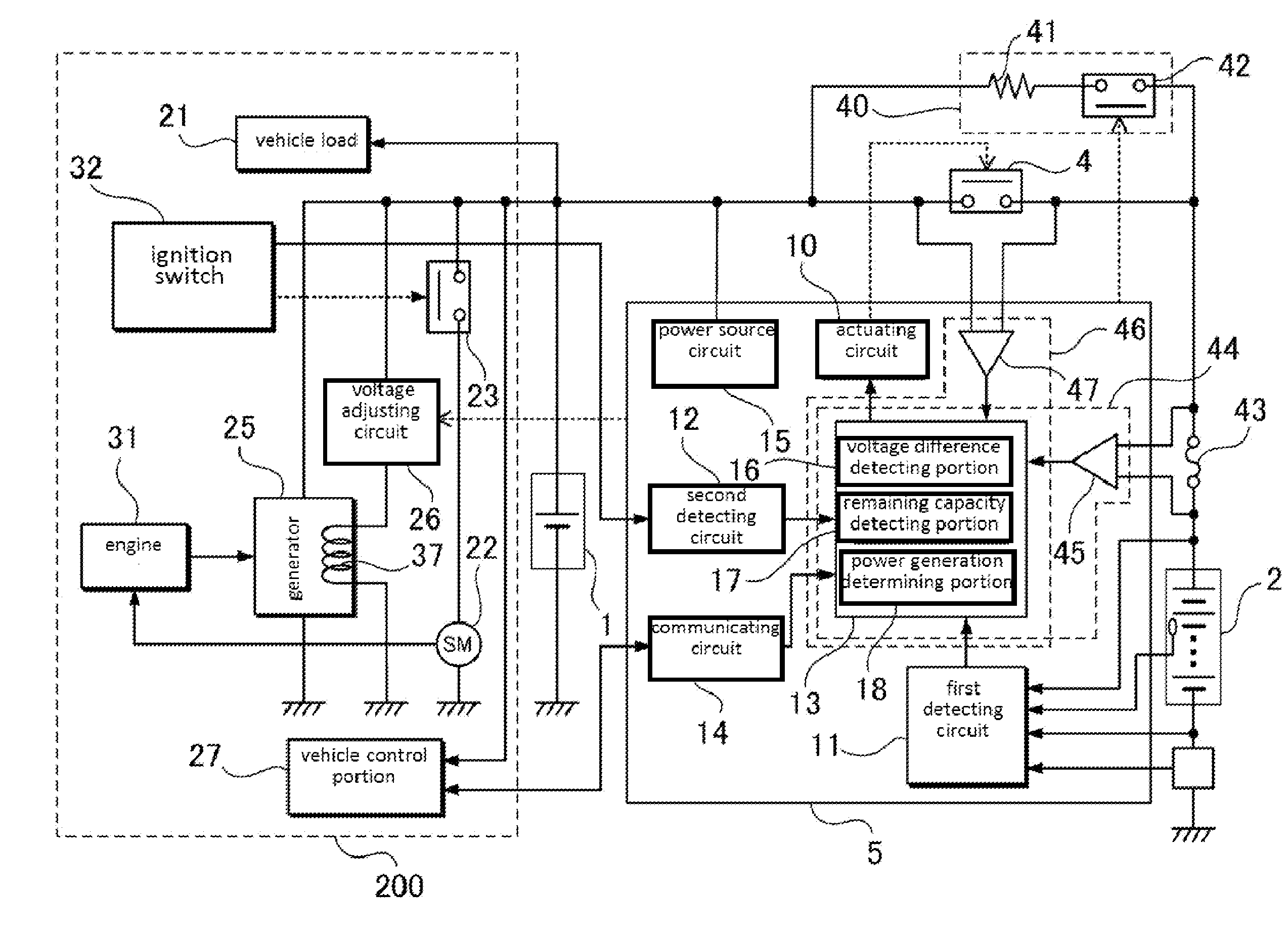
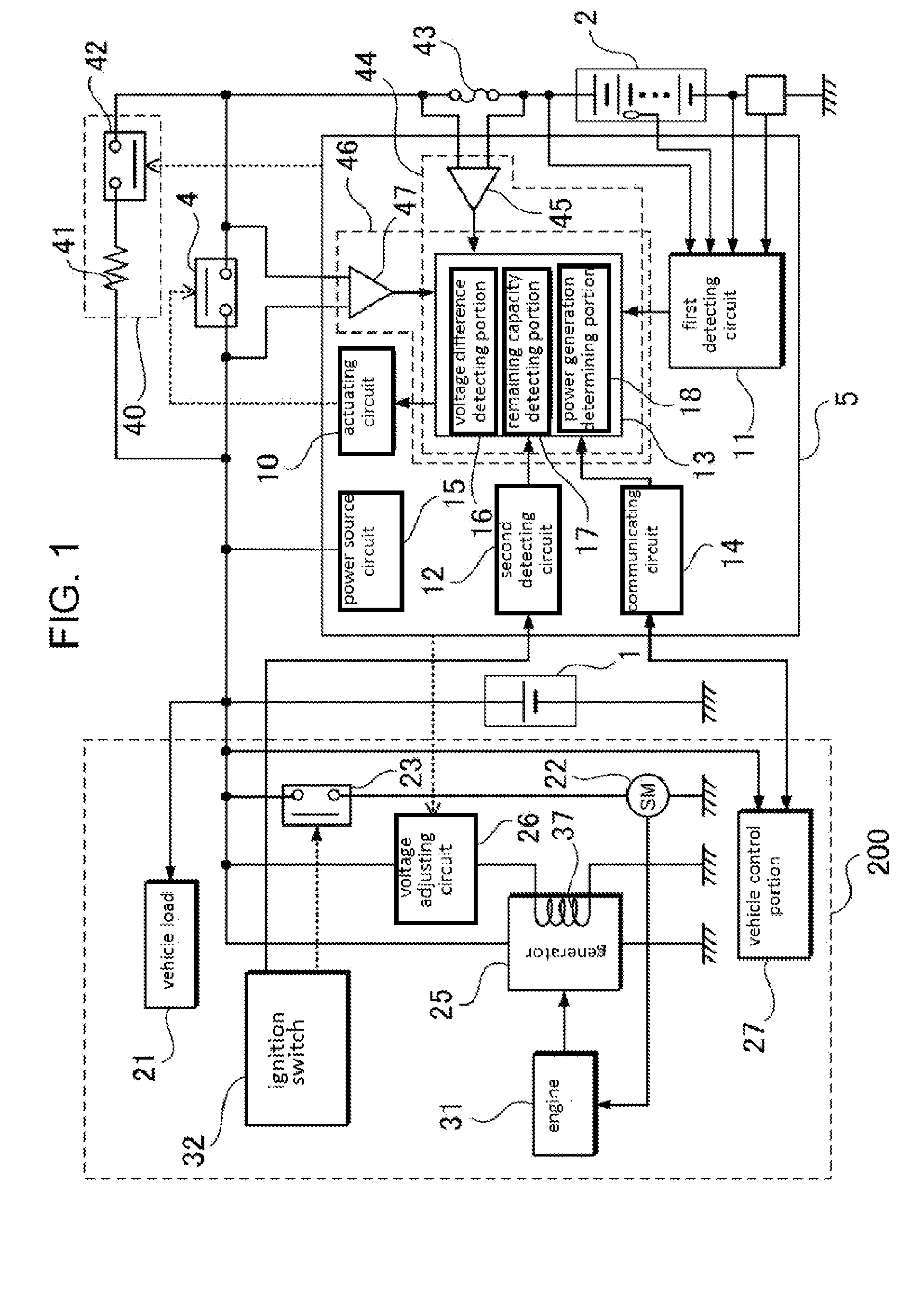
[0029]In a vehicle power supply device shown in FIG. 1, a generator 25 driven by regenerative braking, and an idle stop function are installed in a vehicle 200, then a fuel efficiency of the vehicle 200 is improved. As the generator 25 driven by regenerative braking improves the fuel efficiency, the vehicle power supply device of this embodiment can be installed in the vehicle 200 without the idle stop function. The power supply device show...


PUM


Abstract

A vehicle power supply device comprises a first battery connectable to a starter motor, a vehicle load, and a generator, a second battery different from the first battery in electric characteristics, a connecting switch connected between the first and second batteries, and connecting the first and second batteries in parallel in an ON state of the connecting switch, and a control circuit controlling the connecting switch. In the ON state of the connecting switch, the generator charges the first and second batteries. The control circuit controls to change to the OFF state of the connecting switch in a state of providing electric power to the starter motor, or in a state of detecting an open condition including an abnormal state of the first battery and/or the second battery, and to hold the connecting switch in the ON state in a normal state in which the open condition is not detected.

Description

TECHNICAL FIELD[0001]The present invention is related to a vehicle power source device which provides electric power to a starter motor or electric devices installed on the vehicle, and a vehicle equipped with the power supply device.BACKGROUND ART[0002]A vehicle power source device in the following is developed. In the vehicle power source device, plural batteries which are different in the electric characteristics, for example, a lead batter and a lithium ion battery are connected in parallel, then the lithium ion battery has a higher energy density than the lead batter.(see patent literature 1)[0003]In the power source device of patent literature 1, the lead batter is connected to the lithium ion battery as a high energy density battery. In this power source device, without via a DC / DC converter, the lead battery and the lithium ion battery are connected in parallel. In this power source, both the lead battery and the lithium ion battery are charged by a generator, and also provi...

Claims


Application Information

Patent Timeline
Patent Type & Authority Applications(United States)
IPC IPC(8): B60R16/033
CPCB60R16/033H02J7/16H01M10/4207H01M16/00H02J7/1423H01M2220/20H02J2310/40Y02E60/10H02J7/00302H02J7/00306H02J7/0049
Inventor SAKATA, HIDEKI
Owner SANYO ELECTRIC CO LTD
Why Eureka
Try Eureka