Motor and method for manufacturing stator therefor

a stator and motor technology, applied in the direction of stator/rotor body manufacturing, magnetic circuit shape/form/construction, windings, etc., can solve the problem of not being able to achieve a sufficient degree of simplification in and achieve the effect of simplifying the winding and wiring process and facilitating the process of forming windings

Active Publication Date: 2015-02-05
PANASONIC INTELLECTUAL PROPERTY MANAGEMENT CO LTD
View PDF2 Cites 12 Cited by
  • Summary
  • Abstract
  • Description
  • Claims
  • Application Information

AI Technical Summary

Benefits of technology

[0008]According to the above structure, it becomes possible to carry out the process of forming windings on the core assembly having the core pieces aligned in a strip form, as well as the work of wiring the windings to provide the neutral point only at one side of the core assembly, or the one end to which the phase winding is routed from the other end. In an embodiment of this invention, it is therefore not necessary to do such a complicated work as forming windings on an annularly shaped stator core, thereby helping to carry out the winding and wiring processes easily.
[0009]As described, the present invention can provide the motor having a structure capable of simplifying the winding and wiring processes, and the method for manufacturing the stator of the motor since it can facilitate the process of forming the windings on the core assembly as well as the work of wiring the windings to form the neutral point only at one end of the core assembly.

Problems solved by technology

In other words, it requires a task of complicated wiring work in the wiring step of the windings of the stator assembly in order to complete the winding and wiring process of the annularly-shaped stator core, and it hence gives rise to a problem of not being able to achieve a sufficient degree of simplification in the winding and wiring process including the process of connecting the neutral wires.

Method used


Image

  • Motor and method for manufacturing stator therefor
  • Motor and method for manufacturing stator therefor
  • Motor and method for manufacturing stator therefor

Examples


Embodiment Construction

[0019]Description is provided hereinafter of a motor and a method for manufacturing a stator of the motor according to an exemplary embodiment of the present invention with reference to the accompanying drawings.

Exemplary Embodiment

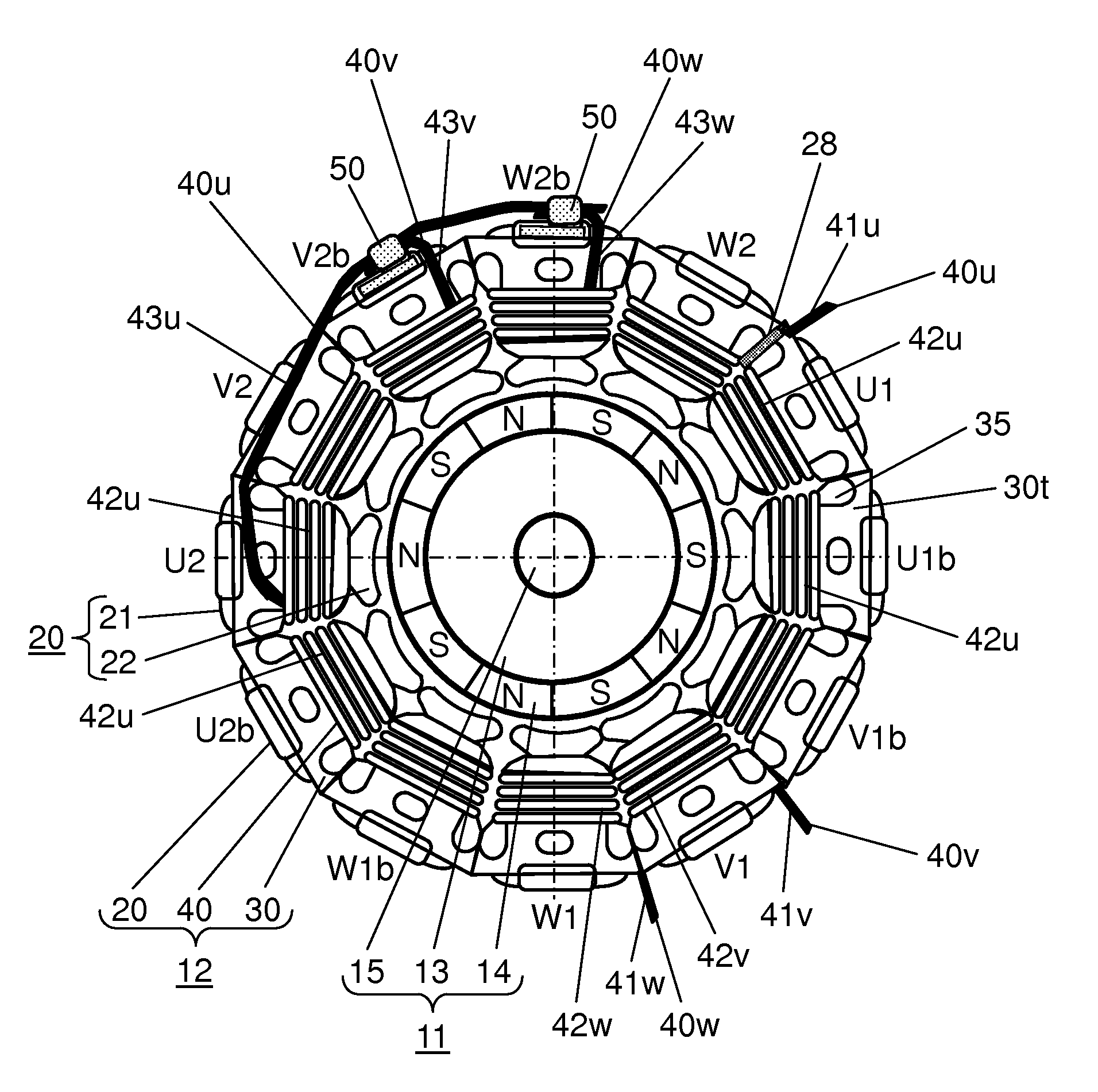
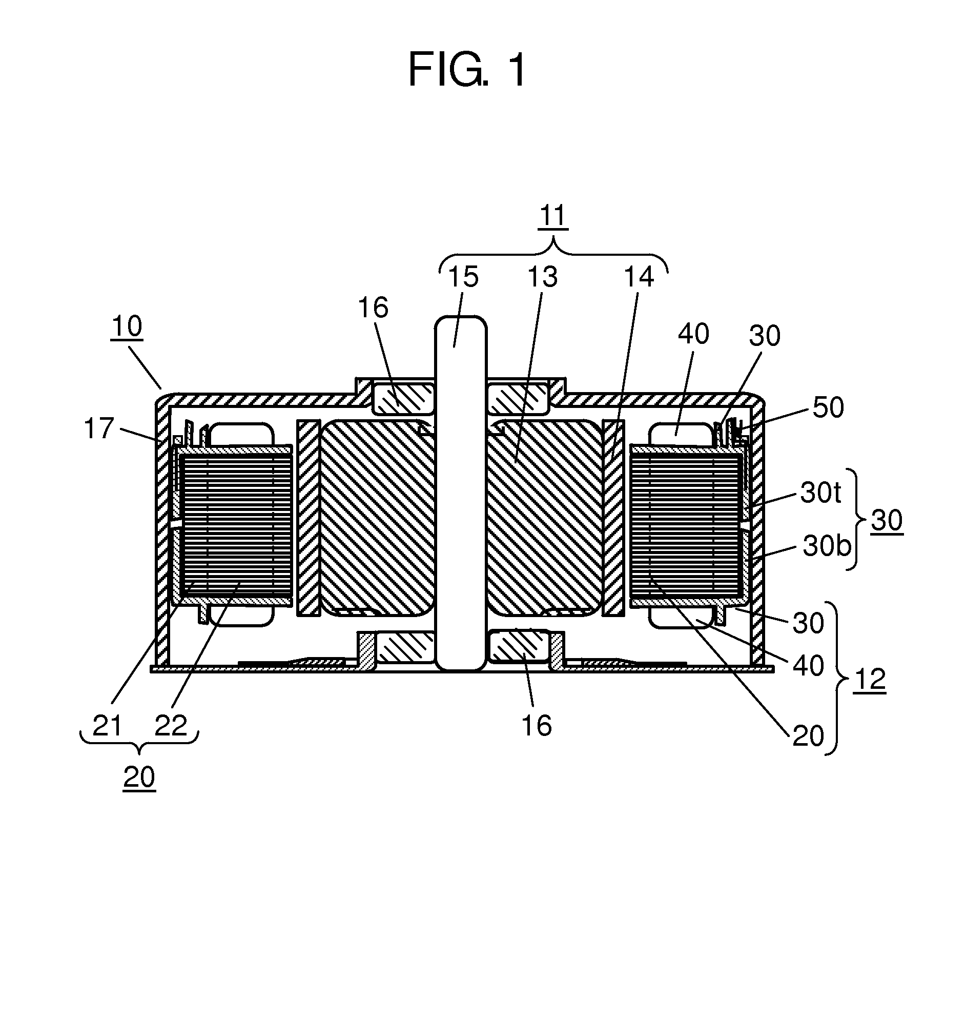
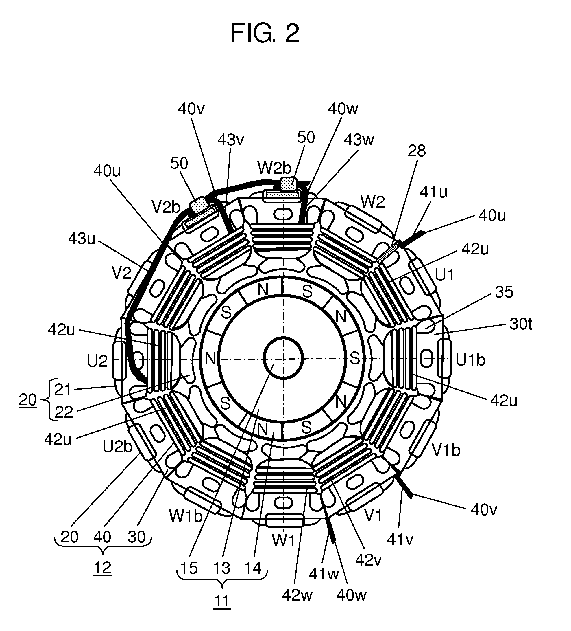
[0020]FIG. 1 is a sectional view of motor 10, and FIG. 2 is a top view of motor 10 showing a main portion thereof, according to one exemplary embodiment of the present invention. In this exemplary embodiment, description is provided of an example of inner-rotor brushless motor having a rotor disposed to an inner side of a stator. This brushless motor is electrically driven by a three-phase alternating current (ac) power supply having U phase, V phase and W phase that are different in phase angle of 120 degrees from one another. In addition, windings of the individual phases of this brushless motor are formed into a Y-connection in which end terminals of these windings are electrically connected as a neutral point to make three-phase driving.

[0021]Motor 10...


PUM

PropertyMeasurementUnit
phase angleaaaaaaaaaa
electricallyaaaaaaaaaa
ac currentaaaaaaaaaa

Abstract

A stator core is formed by deforming a core assembly having core pieces coupled in a strip form into an annular shape, and by joining both ends of the core assembly together to make a core-fastening portion. Individual phase windings are routed from one end of the core assembly toward another end. Lead portion (43v) of phase winding (40v) and lead portion (43w) of phase winding (40w) make up respective wire terminals. Lead portion (43u) of another phase winding (40u) is extended through a plural number of the core pieces in a direction of the lead portions (43v and 43w), and a wire terminal of the extended lead portion (43u) and the wire terminals of the other lead portions (43v and 43w) are electrically connected to provide a neutral point of three-phase Y-connection circuit.

Description

TECHNICAL FIELD[0001]The present invention relates to a structure of a stator of a motor that is driven by a three-phase alternating-current power supply, and a method for manufacturing the stator.BACKGROUND ART[0002]Numerous techniques have hitherto been proposed in which methods of winding coil wires as well as structures of windings wound on stator cores, in order to improve efficiency of winding work and space factors of the windings inside slots of motor stators of such a type that is driven by a three-phase power supply (refer to Patent Literature 1, for example).[0003]Patent Literature 1 provides an improvement of a connecting structure of neutral wires to form a neutral point of the three-phase Y-connection, and simplifies the connection of windings in a stator. That is, in the stator having a plurality of magnetic polar teeth along the circumferential direction, neutral wires of coils of any two phases among the three phases are connected individually to a neutral wire of t...

Claims


Application Information

Patent Timeline
Patent Type & Authority Applications(United States)
IPC IPC(8): H02K3/28H02K15/095H02K3/34H02K15/02H02K1/14H02K3/18
CPCH02K3/28H02K1/148H02K15/095H02K3/345H02K15/022H02K3/18H02K3/522H02K15/0081H02K2203/06Y10T29/49009
Inventor OKINAGA, KINJIROUSEKI, YASUTAKEIIDA, TOMOMITSUYASUNO, MASATOHIDAKA, MASAHITO
Owner PANASONIC INTELLECTUAL PROPERTY MANAGEMENT CO LTD
Why Eureka
Try Eureka