
Recording apparatus

Active Publication Date: 2015-02-05
SEIKO EPSON CORP
View PDF3 Cites 1 Cited by
  • Summary
  • Abstract
  • Description
  • Claims
  • Application Information

AI Technical Summary

Benefits of technology

The present invention aims to provide a simple and precise recording method for a target recording medium that has a lens layer on one side. The invention is designed to be easy to handle and can achieve high-quality recording using a simpler method.

Problems solved by technology

Here, since the target recording medium which is provided with the lenticular lens has high resilience and low flexibility compared to normal sheets, there are restrictions on the transport path such as that it is not possible to carry out transporting on a transport path with a high degree of curvature.
However, when forming a transport path which extends with a linear shape in one direction, for example, from the front of the apparatus toward the side of the rear surface or from the side of the rear surface to the front, the feeding side and the discharge side of the target recording medium are different and the ease of handling is reduced when recording is performed.
In this case, there are cases where the lens which is formed at the edge of the target recording medium is in a defective state of not being cut into a perfect semi-cylindrical shape.
However, in a case where the cutting position is positioned in the middle of a lens element, the lens element at the cutting position will not have a perfect semi-cylindrical shape.
Accordingly, when recording starts with a slicing surface of the lens element with an imperfect semi-cylindrical shape as a reference position, an image which is to be recorded originally on one of the lens elements is recorded across another lens element which is adjacent and it is not possible to favorably obtain the various types of visual effects described above as a result.
In a case of performing so-called borderless recording where recording is performed without a margin at the end sections of the second target recording medium, there is a concern that a portion of liquid, which is discarded in a region which is separated from the end section of the second target recording medium, will float due to becoming a mist, foul the second target recording medium by being reattached to the second target recording medium, and have an adverse effect on the constituent components of the apparatus due to becoming attached.

Method used


Image

  • Recording apparatus
  • Recording apparatus
  • Recording apparatus

Examples


Embodiment Construction

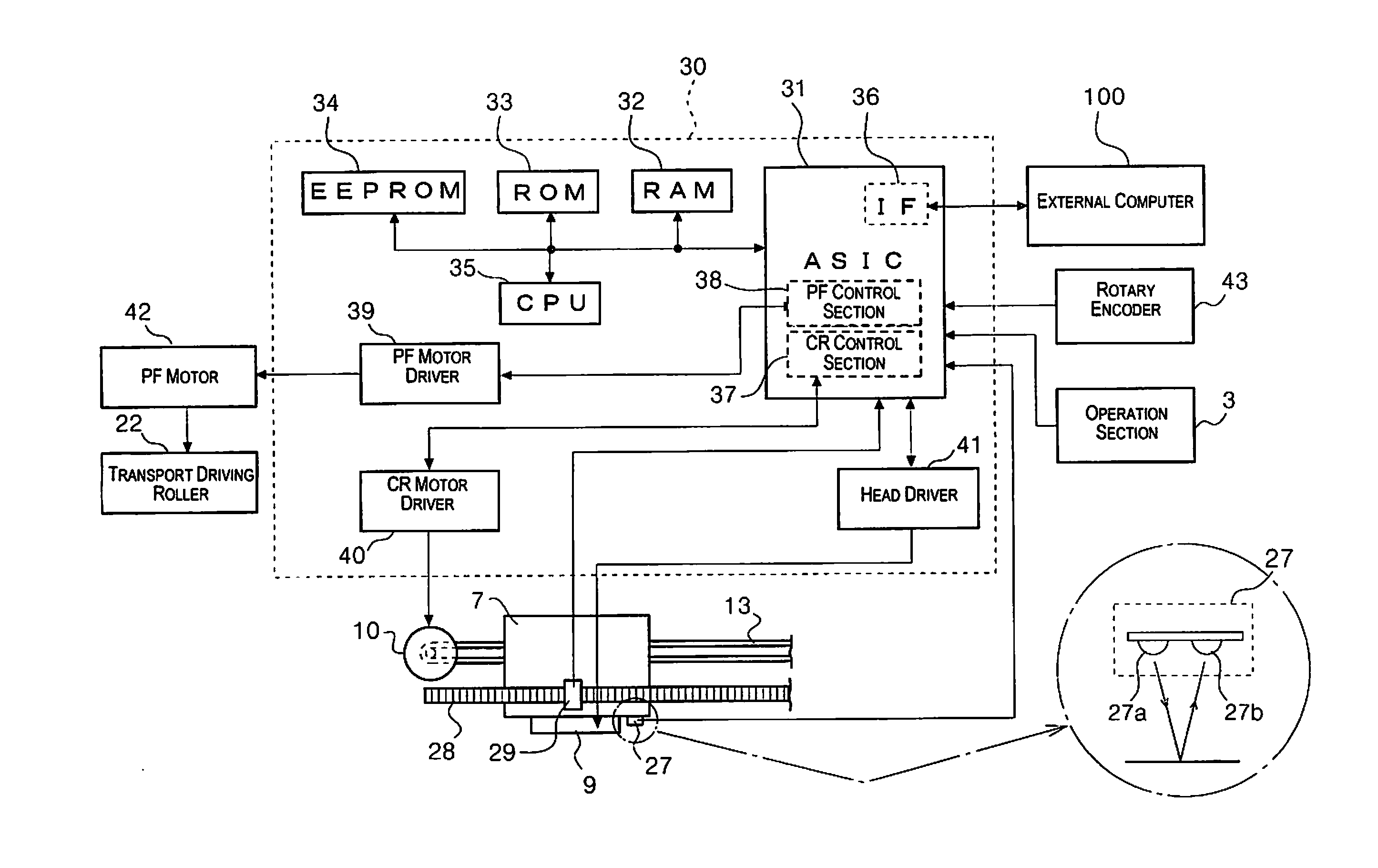
[0077]Below, an embodiment of the present invention will be described based on the diagrams, but the present invention is not limited to the embodiment described below and various modifications are possible within the scope of the inventions which are described in the scope of the claims and embodiments of the present invention will be described later under the premise that these embodiments are also included within the scope of the present invention.

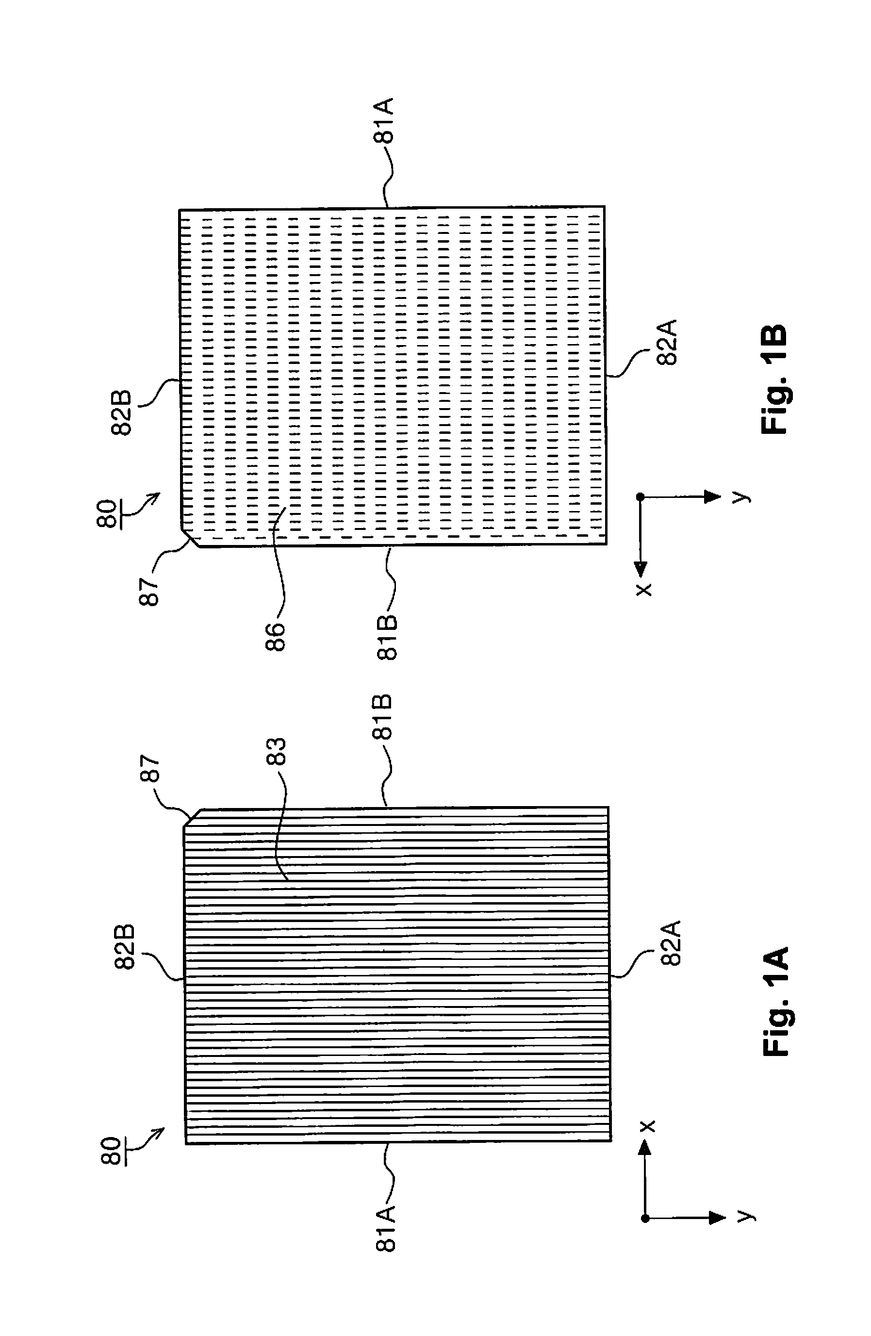
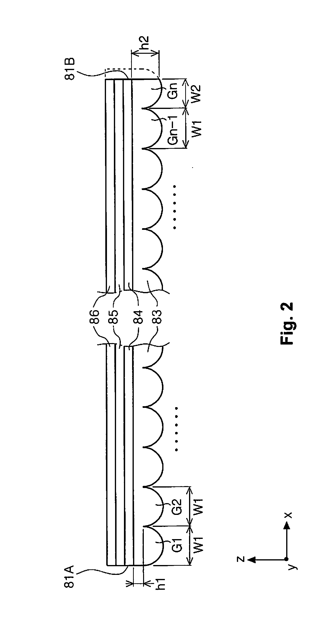
[0078]FIG. 1A is a planar diagram where a lens sheet 80 which is an example of a target recording medium according to the present invention is viewed from a lens layer 83 side, FIG. 1B is a planar diagram where the lens sheet 80 is viewed from an ink absorbing layer 86 side, FIG. 2 is a cross sectional diagram where the lens sheet 80 is sliced along an x-z plane, FIG. 3 is a cross sectional diagram where an end surface on one side of the lens sheet 80 in an x direction is sliced along the x-z plane, and FIGS. 4A to 4C are diagrams illus...


PUM


Abstract

A lens sheet is provided with a lens layer which is formed by arranging lenses, which extend in a y direction as a first direction, in a plurality of lines in an x direction as a second direction which is a direction which is orthogonal to the first direction, and an ink absorbing layer which configures a surface on the opposite side with regard to a surface which is configured by the lens layer, where the thickness of an edge which is an end surface on one side of the lens layer in the x direction is thinner than the thickness of an edge which is an end surface on the other side. The printer performs recording from the edge which is a reference side toward the edge on the opposite side.

Description

CROSS-REFERENCE TO RELATED APPLICATIONS[0001]This application claims priority to Japanese Patent Application No. 2013-161366 filed on Aug. 2, 2013, Japanese Patent Application No. 2013-161389 filed on Aug. 2, 2013, Japanese Patent Application No. 2013-161401 filed on Aug. 2, 2013, Japanese Patent Application No. 2013-161420 filed on Aug. 2, 2013, and Japanese Patent Application No. 2013-161436 filed on Aug. 2, 2013. The entire disclosures of Japanese Patent Application Nos. 2013-161366, 2013-161389, 2013-161401, 2013-161420, and 2013-161436 are hereby incorporated herein by reference.BACKGROUND[0002]1. Technical Field[0003]The present invention relates to a recording apparatus which performs recording onto a target recording medium which is configured such that a surface on one side is a lens layer which is configured by a plurality of lenses and a surface of the other side is a recording layer where recording is possible using a recording head.[0004]2. Related Art[0005]Among printe...

Claims


Application Information

Patent Timeline
IPC IPC(8): B41J2/045
CPCB41J2/04501B41J3/60B41J11/009B41J13/0018B41J13/103B41J19/142
Inventor YOSHIHISA, YASUHIKOYAMADA, KATSUMISHIROTORI, HIROSHISUZUKI, KATSUHITOSONEHARA, TOMIO
Owner SEIKO EPSON CORP
Learn More